Video and Vision Processing Suite Intel® FPGA IP User Guide
A newer version of this document is available. Customers should click here to go to the newest version.
14.2. Clocked Video to Full-Raster Converter Parameters
| Parameter | Values | Description |
|---|---|---|
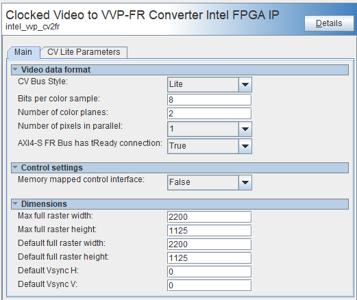
| Video Data Format | ||
| CV Bus Style | Lite, CVI or CVO | Select which sideband signals the IP drives, and which signals are available in Platform Designer. A second tab allows you to parameterize the CV bus style. |
| Bits per color sample | 6 to 16 | Number of bits per color sample. |
| Number of color planes | 1 to 4 | Number of color planes in a pixel. |
| Number of pixels in parallel | 1, 2, 4 or 8 | Number of pixels transmitted every clock. |
| AXI4S FR Bus has tReady connection | True or False | Select true so the streaming full-raster interface contains the AXI4-S tReady signal. Select false to remove, the tReady signal. |
| Control Settings | ||
| Memory-mapped control interface | True or False | Select True to turn on the CPU interface and associated signals. Select False to remove the CPU interface and for all the CPU registers to use default values. |
| Separate clock for control interface | True or False | Select True to include the signal cpu_clock in Platform Designer. It is asynchronous to the video domain. Select False so the CPU interface uses the signal vid_clock. |
| Dimensions | ||
| Max full-raster width | 1 to 65535 | The maximum width of raster that this IP passes. |
| Max full-raster height | 1 to 65535 | The maximum height of raster this IP passes. |
| Default full-raster width | 1 to 65535 | The width of the raster. The CPU can override this value. |
| Default full-raster height | 1 to 65535 | The height of the raster. The CPU can override this value. |
| Default Vsync H | 1 to 65535 | The default pixel position of the rising edge of the vertical timing signal (vsync or vblank) The CPU can override this value. |
| Default Vsync V | 1 to 65535 | The default line where the rising edge of the vertical timing signal (vsync or vblank) occurs. The CPU can override this value. |
| Parameter | Values | Description |
|---|---|---|
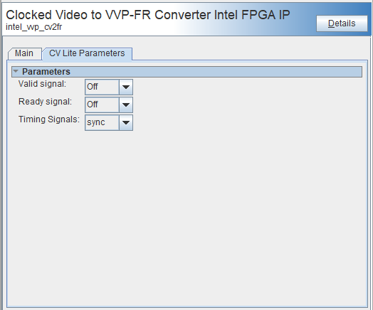
| Parameters | ||
| Valid signal | On or off | When you select Lite the IP includes an optional data valid input signal, cv_vid_in_valid. Turn on to turn on this input in the IP. Platform Designer includes or removes the signal from the cv_vid_in conduit as appropriate. |
| Ready signal | On or off | When you select Lite the IP includes an optional data ready output signal, cv_vid_in_ready. Turn on to turn on this output in the IP. Platform Designer includes or removes the signal from the cv_vid_in conduit as appropriate. |
| Timing Signals | sync, blank, or both | Select which timing are available. Platform Designer includes or removes the signals from the cv_vid_in conduit as appropriate |
| Parameters | Values | Description |
|---|---|---|
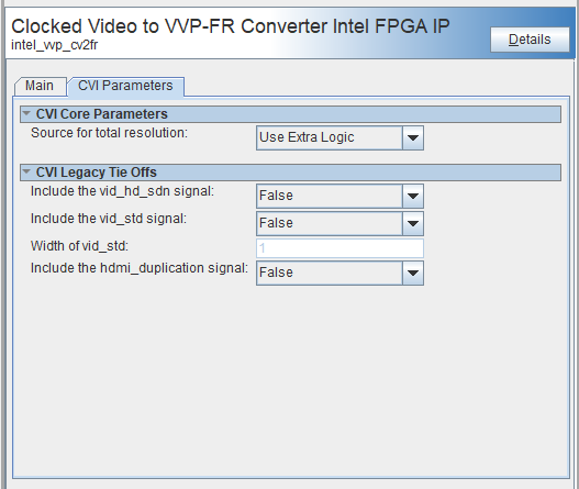
| CVI Core Parameters | ||
| Source for total resolution | Use Extra Logic or Use External Signals | The IP requires the height and width of the raster. Determine this information using additional logic within the IP, or get the information from optional input signals. This parameter selects the source for the raster dimensions. Platform Designer includes or removes the signals from the cv_vid_in conduit as appropriate |
| CVI Legacy Tie Offs | ||
| Include the vid_hd_sdn signal | True or False | Select True to add this signal to the cv_vid_in conduit. The signal has no function within the IP and is included for connectivity within Platform Designer. |
| Include the vid_std signal | True or False | Select True to add this signal to the cv_vid_in conduit. The signal has no function within the IP and is included for connectivity within Platform Designer. |
| Width of vid_std | 1 to 16 | The width of the vid_std signal. |
| Include the hdmi_duplication signal | True or False | Select True to add this signal to the cv_vid_in conduit. The signal has no function within the IP and is included for connectivity within Platform Designer. |
| Parameters | Values | Description |
|---|---|---|
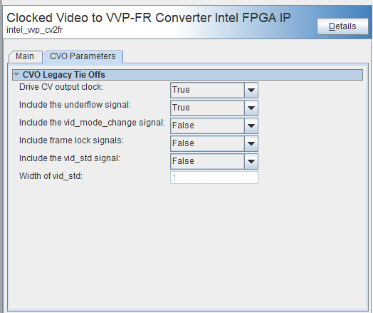
| CVO Legacy Tie Offs | ||
| Drive CV Output Clock | True or False | Select True to add this signal to the cv_vid_in conduit. The signal has no function within the IP and is included for connectivity within Platform Designer. |
| Include the underflow signal | True or False | Select True to add this signal to the cv_vid_in conduit. The signal has no function within the IP and is included for connectivity within Platform Designer. |
| Include the vid_mode_change signal | True or False | Select True to add this signal to the cv_vid_in conduit. The signal has no function within the IP and is included for connectivity within Platform Designer. |
| Include the frame lock signals | True or False | Select True to add this signal to the cv_vid_in conduit. The signal has no function within the IP and is included for connectivity within Platform Designer. |
| Include the vid_std signal | True or False | Select True to add this signal to the cv_vid_in conduit. The signal has no function within the IP and is included for connectivity within Platform Designer. |
| Width of vid_std | 1 to 16 | Select the width of the vid_std signal. |