Quartus® Prime Pro Edition User Guide: Design Compilation
A newer version of this document is available. Customers should click here to go to the newest version.
1.7.3.7. Example: Using SDC-on-RTL Features
You can work with both new and pre-existing designs that incorporate components from diverse sources, including Verilog, VHDL, IPs, and Platform Designer. Suppose your designs contain nodes that require constraint definitions, such as clocks, generated clocks, or asynchronous paths, across various hierarchy levels. In that case, you can efficiently target them using SDC-on-RTL constraints. It is imperative that your chosen design successfully passes the Analysis & Elaboration stages within the compilation flow for seamless and effective testing process.
You can control the number of stages generated during the Analysis & Elaboration using the RTL Analysis Debug Mode option under Project > Settings. This mode is off by default, which means only Elaborated and Swept checkpoints are available, and Instrumented and Constrained checkpoints are unavailable. When you enable this mode, all four checkpoints become available.
The following steps demonstrate the process of setting up timing constraints for your designs by targeting RTL node names:
- Click New in the left-hand Tasks pane. The New dialog appears.
- Click SDC File targeting RTL Names (Read and stored after elaboration).
Figure 54. New Dialog Box
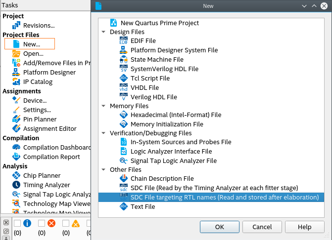
- Click OK.
- Within the new SDC-on-RTL file, formulate a comprehensive set of constraints targeting nodes by their RTL names. For information about how to obtain a list of the supported commands, refer to Creating Constraints in SDC-on-RTL SDC Files.
- Ensure the constraint targets are correct and the selected design passes the Analysis & Elaboration compilation stage as the constraints are read during this stage and applied to the elaborated netlist. This step is pivotal as it empowers the software to generate a database of your design. Additionally, it grants access to various checkpoints from where you can access the RTL Analyzer.
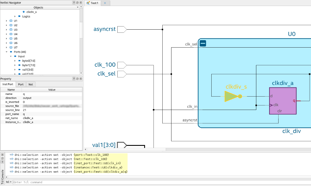
Note: The RTL Analyzer assists you in locating specific netlist nodes within your design that require constraint application. It allows you to navigate your design and select your desired target nodes. Subsequently, you can use corresponding Tcl commands generated within the Tcl console to extract hierarchical node names from the Tcl commands. This process streamlines the task of implementing constraints on the netlist nodes. For more information about the RTL Analyzer, refer to Exploring the RTL Analyzer.Figure 55. Locating Specific Netlist Nodes in the RTL Analyzer
Alternatively, you can locate nodes within your target netlist using the Find tool, which is available from the Edit menu in the RTL Analyzer. The Find tool allows you to search objects within the updated database from the checkpoint accessed.
Figure 56. Find Dialog in the RTL Analyzer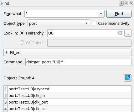
In addition, you can create your collections by focusing on the inputs and outputs of your design through the use of the get_ports command. Within your design, you can locate specific nets using the get_nets command or target pins using the get_pins command.
After establishing your timing constraints in your designs, use the following examples as a guide to set up your constraints, specifically focusing on RTL node names, thereby ensuring precision and efficiency throughout your design process.
Targeting Pins of Top-level Instances
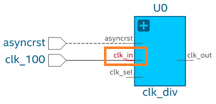
In certain scenarios, it is necessary to constrain pins of top-level instances. For example, when defining clocks and reset inputs, you can utilize the get_pins Tcl command followed by the hierarchical pin name to filter each pin as shown in the following:
get_pins U0|clk_in
This Tcl command returns the input pin clk_in in the instance U0.
create_clock -name clk_input -period 10 [get_pins U0|clk_in]
create_generated_clock -name clk_output -source [get_pins U0|clk_in] -divide_by 2 [get_pins U0|clk_out]
Targeting Pins in Cells
When constraining your design, you might need to target cell pins to apply constraints. In such scenarios, you can use the get_pins Tcl command and RTL names to locate specific cell pins, such as clk or d inputs and q outputs. For example:
get_pins U6|reg_a[0]|clk
get_pins U6|reg_a[0]|d
get_pins U6|reg_a[0]|q
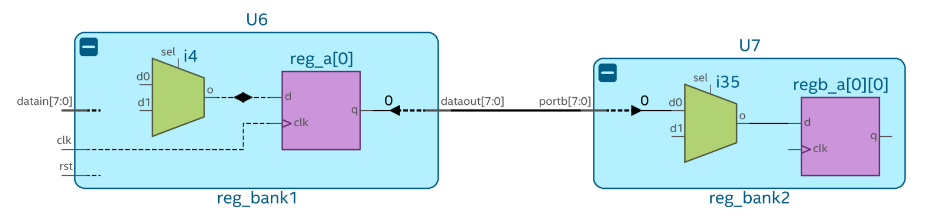
These Tcl commands return specific pins of the reg_a[0] register in the U6 instance. You can use the returned collection to constrain paths. For example, from U6|reg_a[0] to U7|regb_a[0][7] as follows:
set_false_path -from [get_pins U6|reg_a[0]|clk] -to [get_pins U7|regb_a[0][0]|d]
Targeting Pins Using Wildcards
Within your design, you might need to constrain several pins with similar properties and names. In this case, use wildcards to filter the results.
The get_pins command can target buses porta or portb of U7, as shown in the following:
get_pins U7|porta[*]
get_pins U7|portb[*]
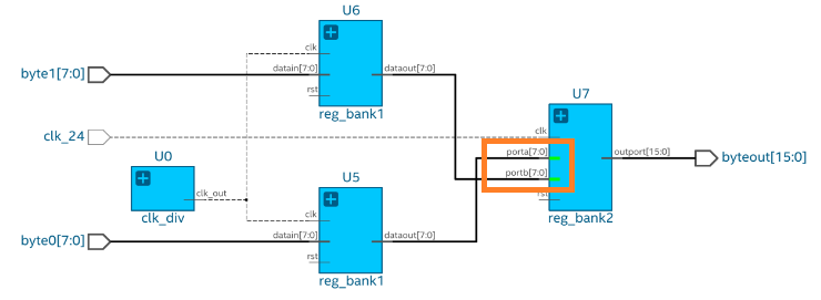
The Tcl command returns a collection of pins from porta[0] to porta[7] and from portb[0] to portb[7]. You can use the returned collection to constrain all objects simultaneously, as shown in the following:
set_false_path -from [get_pins U5|rega*|clk] -to [get_pins U7|porta[*]]
set_false_path -from [get_pins U6|rega*|clk] -to [get_pins U7|portb[*]]
Example 4. Applying Constraints at Deeper Hierarchies
Within your design, you can apply constraints at different levels of hierarchy using the pipe character (|) to separate hierarchy levels of instances. Constraints are applied when the hierarchy levels match and the string values, including wildcards, match the pin names. For example:
get_pins U3|U0_lv1|U0_lv2|U0_lv3|flag
The fundamental timing analysis flow requires executing the fitter to elaborate the timing netlist before applying any constraints. In the following example, suppose you intend to constraint a generated clock buried deep within module A:
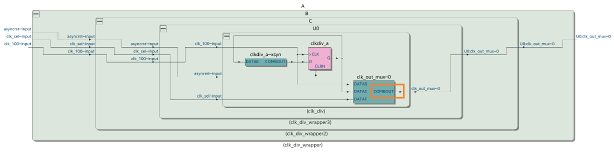
To achieve this, locate the cell clk_out_mux where the constraint must be applied and identify the pin name COMBOUT. This process often results in a complex path name that can be challenging to decipher, especially when module names are intricate (unlike straightforward names, such as A|B|C). Additionally, suppose the hierarchy evolves in the future. In that case, you must rerun the fitter and delve into the design again to derive the updated path, which can lead to inconsistencies between the design and the constraint targets. You can target the COMBOUT pin as follows:
get_pins A|B|C|U0|clk_out_mux~0|combout
SDC-on-RTL also offers an efficient means of constraint propagation, enabling you to apply constraints at module boundaries. It ensures that these constraints seamlessly extend to the corresponding leaf instances during the synthesis stage. For instance, revisit the previous example, in which the clock constraint embedded within module A can be established using SDC-on-RTL constraints at the module A's boundaries, specifically focusing on the clk_out pin.
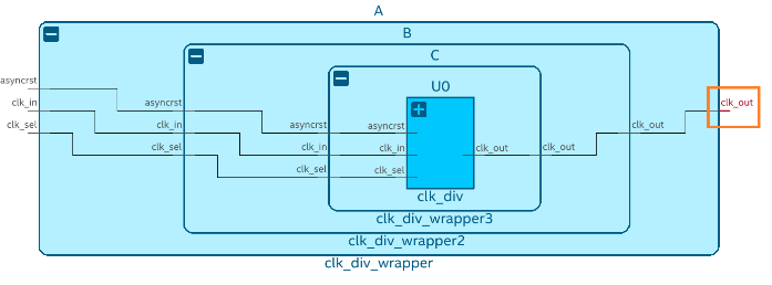
To target the clk_out pin of module A, use the following filter:
get_pins A|clk_out
By directing your attention towards pins located at the boundaries of abstract blocks, you gain the flexibility to modify the internal instance hierarchy as needed. Constraints remain effective even if you decide to rename an internal instance within your module, for instance, changing it from A|B|C|U0 to A|X|Y|U0. Importantly, this can be accomplished without requiring alterations to your existing constraints. This demonstrates the robust capabilities of SDC-on-RTL, allowing you to concentrate on boundary pins rather than navigating complex hierarchies. This approach ensures constraint accuracy and simplifies constraint management.
After creating the constraints, rerun the Analysis & Elaboration on the compilation dashboard so that constraints are read and applied to your design. Open the constrained checkpoint of the RTL Analyzer and carefully select the nodes where the constraints were applied. Utilize the Property Viewer to verify the correct application of constraints to these nodes. For additional information, refer to Inspecting SDC-on-RTL Constraints.
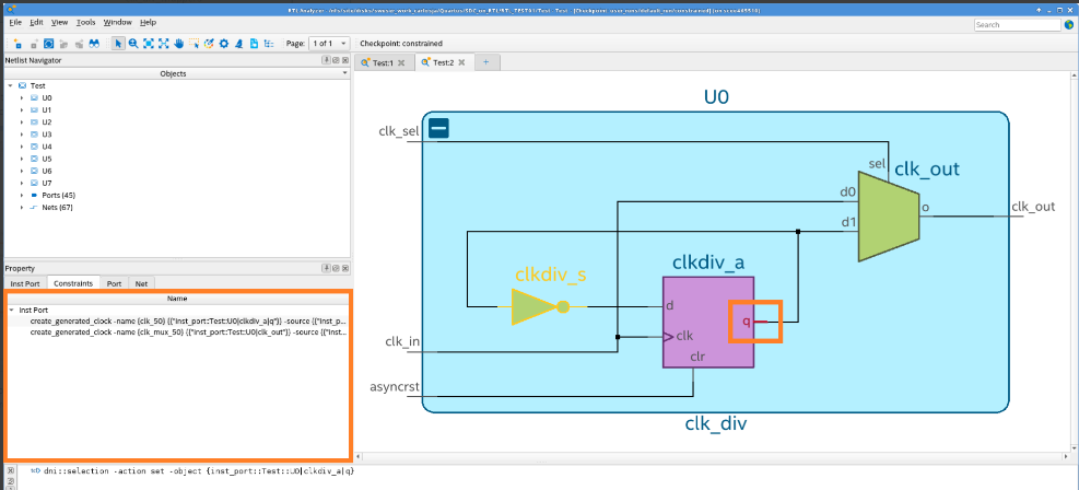
Utilize the Quartus® Prime software's additional tools to explore and confirm that all SDC constraints were read and successfully applied. Tools like the Constraints viewer launched from the RTL Analyzer can assist you in verifying and cross-probing the constraints with the Schematic Viewer.
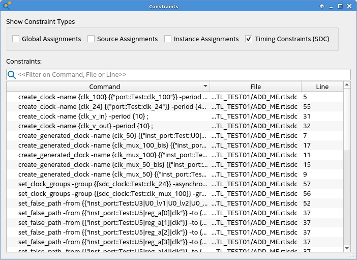
Additionally, the reports under Compilation Report > SDC Constraints folder provide a detailed view of the constraints and their locations. Use the Constraint Propagation Report to view how constraints are propagated as the netlist is transformed and inspect where the constraints end up post optimizations.