Quartus® Prime Pro Edition User Guide: Design Compilation
ID
683236
Date
4/01/2024
Public
A newer version of this document is available. Customers should click here to go to the newest version.
1.1. Compilation Overview
1.2. Using the Compilation Dashboard
1.3. Design Netlist Infrastructure
1.4. Using the Node Finder
1.5. Precompiled Component (PCC) Generation Flow
1.6. Analysis & Elaboration Flow
1.7. Design Synthesis
1.8. Design Place and Route
1.9. Incremental Optimization Flow
1.10. Fast Forward Compilation Flow
1.11. Full Compilation Flow
1.12. Compilation Monitoring Mode
1.13. Exporting Compilation Results
1.14. Integrating Other EDA Tools
1.15. Compiler Optimization Techniques
1.16. Synthesis Language Support
1.17. Synthesis Settings Reference
1.18. Fitter Settings Reference
1.19. Design Compilation Revision History
1.7.3.1. Registering the SDC-on-RTL SDC File
1.7.3.2. Applying the SDC-on-RTL Constraints
1.7.3.3. Inspecting SDC-on-RTL Constraints
1.7.3.4. Creating Constraints in SDC-on-RTL SDC Files
1.7.3.5. Using Entity-Based SDC-on-RTL Constraints
1.7.3.6. Types of SDC Files Used in the Quartus® Prime Software
1.7.3.7. Example: Using SDC-on-RTL Features
1.13.1. Exporting a Version-Compatible Compilation Database
1.13.2. Importing a Version-Compatible Compilation Database
1.13.3. Creating a Design Partition
1.13.4. Exporting a Design Partition
1.13.5. Reusing a Design Partition
1.13.6. Viewing Quartus Database File Information
1.13.7. Clearing Compilation Results
2.1. Factors Affecting Compilation Results
2.2. Strategies to Reduce the Overall Compilation Time
2.3. Reducing Synthesis Time and Synthesis Netlist Optimization Time
2.4. Reducing Placement Time
2.5. Reducing Routing Time
2.6. Reducing Static Timing Analysis Time
2.7. Setting Process Priority
2.8. Reducing Compilation Time Revision History
1.9.2.1.3. Analyzing High Fan-out Nets with Snapshot Viewer
- To run the Place or Route stage of the Fitter, double-click the stage in the Compilation Dashboard.
- After the stage completes, click the Snapshot Viewer icon for that stage in the Compilation Dashboard. The Snapshot Viewer opens.
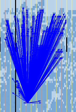
- Under Analyze High Fanout Nets, click Show High Fanout Nets in the Schematic. The path displays and highlights in Tech Map Viewer for further analysis.
- Under Analyze High Fanout Nets, click Show High Fanout Nets in the Chip View. The path displays and highlights in the Chip Planner for further analysis.
Figure 89. Non-Global High Fan-Out Signal in Chip Planner
