V-Series Avalon-MM DMA Interface for PCIe Solutions User Guide
ID
683514
Date
7/31/2018
Public
1. Datasheet
2. Getting Started with the Avalon-MM DMA
3. Parameter Settings
4. Registers
5. Error Handling
6. PCI Express Protocol Stack
7. V-Series Avalon-MM DMA for PCI Express
8. Transceiver PHY IP Reconfiguration
A. Frequently Asked Questions for V-Series Avalon-MM DMA Interface for PCIe
B. V-Series Interface for PCIe Solutions User Guide Archive
C. Document Revision History
1.1. V-Series Avalon-MM DMA Interface for PCIe* Datasheet
1.2. Features
1.3. Comparison of Avalon-ST, Avalon-MM and Avalon-MM with DMA Interfaces for V-Series Devices
1.4. Release Information
1.5. V-Series Device Family Support
1.6. Design Examples
1.7. Debug Features
1.8. IP Core Verification
1.9. Resource Utilization
1.10. V-Series Recommended Speed Grades
1.11. Creating a Design for PCI Express
4.1. Correspondence between Configuration Space Registers and the PCIe Specification
4.2. Type 0 Configuration Space Registers
4.3. Type 1 Configuration Space Registers
4.4. PCI Express Capability Structures
4.5. Intel-Defined VSEC Registers
4.6. Advanced Error Reporting Capability
4.7. DMA Descriptor Controller Registers
4.8. Control Register Access (CRA) Avalon-MM Slave Port
7.1. Understanding the Internal DMA Descriptor Controller
When you select Instantiate internal descriptor controller in the parameter editor, the Avalon-MM with DMA includes an internal DMA Descriptor Controller to manage read and write DMA operations. The DMA Descriptor Controller includes read and write data movers to perform local memory reads and writes. It supports up to 128 descriptors for read and write DMAs. Host software programs the DMA Descriptor Controller internal registers with the location and size of the descriptor table residing in the PCI Express main memory. The descriptor control logic directs the DMA read logic to copy the entire table to its local FIFOs.
Figure 17. Platform Designer Design Example with the Internal DMA Descriptor ControllerThis Platform Designer design example, ep_g3x8_avmm256_integrated.qsys, is available in the <install_dir>/ ip/altera/altera_pcie/altera_pcie_a10_ed/example_design/a10 directory. Refer to Getting Started with the V-Series Avalon-MM DMA for instructions on simulating and compiling this example design. This screen capture filters out some interface types for clarity.
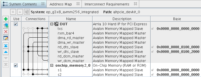
Figure 18. Avalon-MM DMA Block Diagram with the Internal DMA Descriptor ControllerThis block diagram corresponds to the Platform Designer system shown in the previous figure.
This design uses BAR0 and BAR1 to create a 64-bit address to access the DMA Descriptor Controller. These BARs cannot connect to any other interface. If BAR0 must access a different interface, you must use an external DMA descriptor controller. Intel recommends that you select the internal DMA Descriptor Controller if you do not plan to modify this component.
The high-performance BAR2 or BAR2 and BAR3 for 64-bit addresses is available to receive data for other high performance functions.