3.8.7.2. Power-Up Sequence
The figure below shows the power distribution system on the MAX® 10 FPGA 10M50 Evaluation Board.
Figure 9. Power Tree—EK-10M50F484 (Power Solution 1)
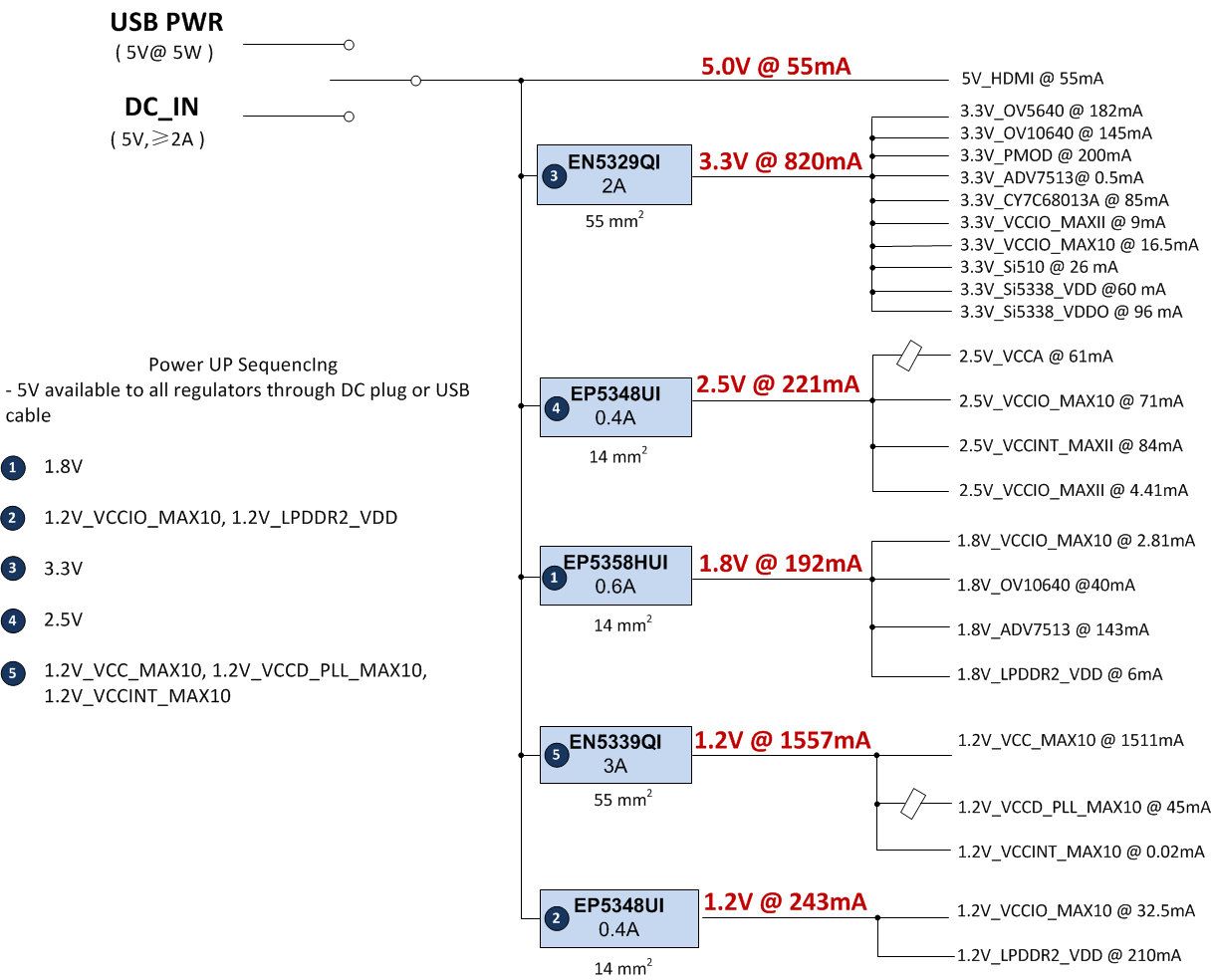
The power up sequence of the MAX® 10 FPGA 10M50 Evaluation Board is shown in the table below.
| Power-Up Sequence | Device | Output Voltage (V) |
|---|---|---|
| 1 | EP5358HUI | 1.8 |
| 2 | EP5348UI | 1.2 |
| 3 | EM5329QI | 3.3 |
| 4 | EP5384UI | 2.5 |
| 5 | EN5339QI | 1.2 |
Figure 10. Power Tree—DK-DEV-10M50F484-C (Power Solution 2)
| Power-Up Sequence | Device | Output Voltage (V) |
|---|---|---|
| 1 | MPM3804GG-C879-Z | 1.8 |
| 2 | MPM3804GG-C879-Z | 1.2 |
| 3 | MPM3632SGPQ-C879-Z | 3.3 |
| 4 | MPM3804GG-C879-Z | 2.5 |
| 5 | MPM3632SGPQ-C879-Z | 1.2 |