Intel® Quartus® Prime Pro Edition User Guide: Timing Analyzer
A newer version of this document is available. Customers should click here to go to the newest version.
2.5.5. Correlating Constraints to the Timing Report
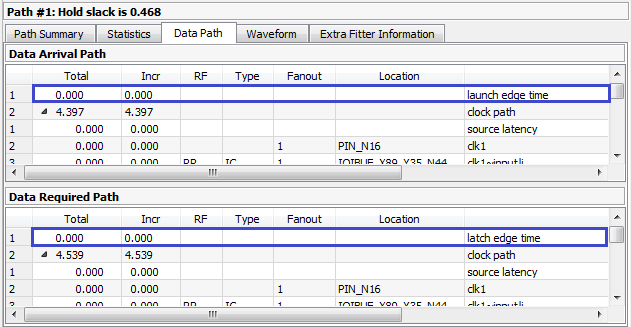
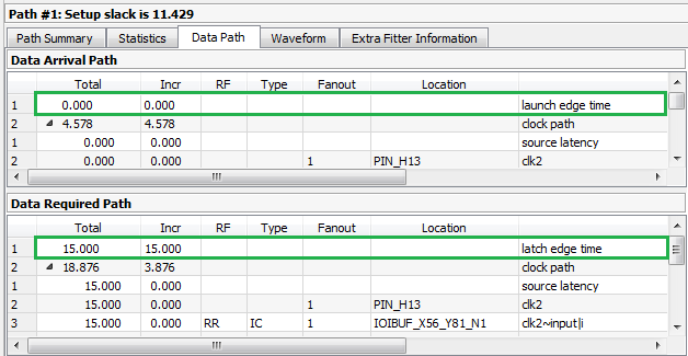
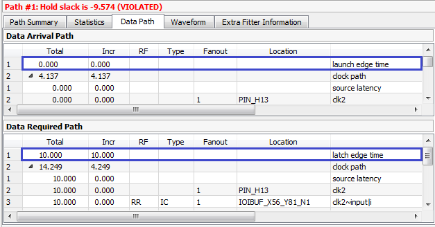
The figures show the results of running Report Timing on a particular path.
create_clock -name clocktwo -period 10.000 [get_ports {clk2}]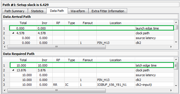
set_multicycle_path -from clocktwo -to clocktwo -setup -end 2
set_multicycle_path -from clocktwo -to clocktwo -hold -end 1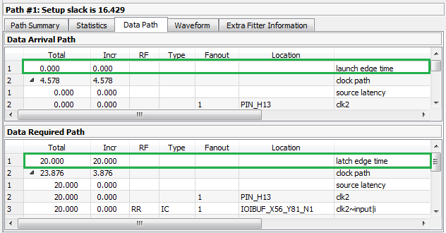
The set_max_delay and set_min_delay constraints explicitly override the setup relationship. Note that the only thing changing for these different constraints are the launch edge time and latch edge times for setup and hold analysis. Every other line item comes from delays inside the FPGA and are static for a given fit. View these reports to analyze how your constraints affect the timing reports.
For I/O, you must add set_input_delay and set_output_delay constraints. These constraints describe delays on signals from outside of the FPGA design that connect to the design's I/O ports. The values of these constraints are the delays of the external signals between an external register and a port on the design. The -clock argument to the set_input_delay and set_output_delay specifies the clock domain that the external signal belongs to, or rather, the clock domain of the external register connected to the I/O port. The -min and -max options specify the worst-case or best-case delay; not specifying either option causes the worst- and best-case delays to be equal. I/O delays display as iExt or oExt in the Type column. An example is an output port with a set_output_delay -max 1.0 and set_output_delay -min -0.5. Refer to "Creating Virtual Clocks" and "Creating I/O Constraints" for more information.
A clock relationship, which is the difference between the launching and latching clock edge of a transfer, is determined by the clock waveform, multicycle constraints, and minimum and maximum delay constraints. The Timing Analyzer also adds the value of set_output_delay as an oExt value. For outputs this value is part of the Data Required Path, since this is the external part of the analysis. The setup report subtracts the -max value, making the setup relationship harder to meet, since the Data Arrival Path must be shorter than the Data Required Path. The Timing Analyzer also subtracts the -min value. This subtraction is why a negative number causes more restrictive hold timing. The Data Arrival Path must be longer than the Data Required Path.