Intel® Quartus® Prime Pro Edition User Guide: Design Compilation
A newer version of this document is available. Customers should click here to go to the newest version.
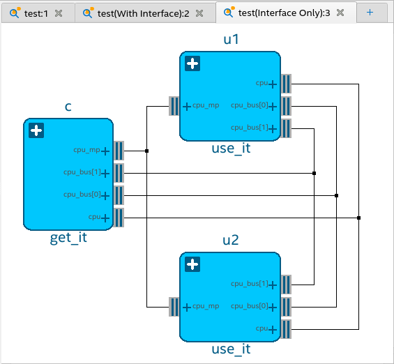
2.3.1.4. Module Interfaces
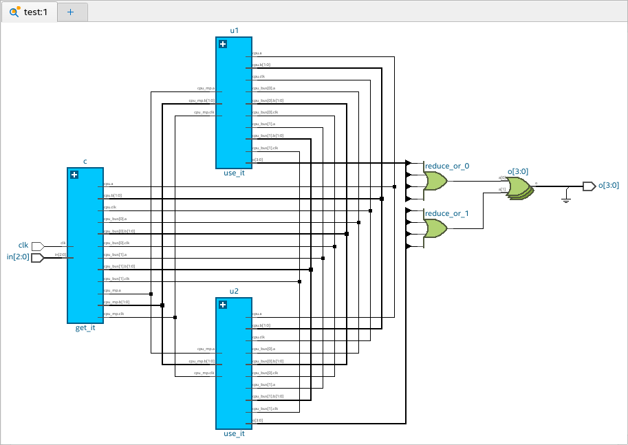
No Interface Mode (Default)
This is the default mode where all ports display individually, even if they are part of an interface.
In the following example, you can observe that all ports for c, u1, and u2 modules are listed without any grouping of ports.
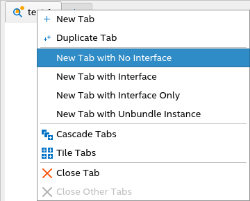
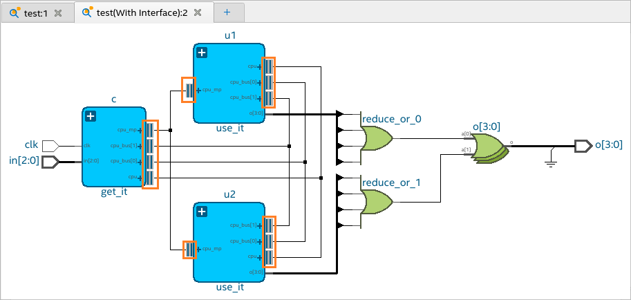
With Interface Mode
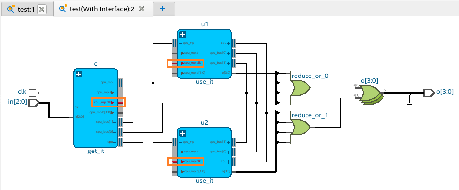
In this mode, all ports of an interface are grouped to show a compact and simplified view of the schematic. Interfaces have an expand button "+" and double vertical lines beside the port. You can expand each interface to view all ports under the interface.
In the following example, you can observe that in the u1 module, all ports that are part of cpu, cpu_bus[0], cpu_bus[1], and cpu_mp interfaces are grouped (indicated by the '+' symbol). Each interface has two dark gray lines marked beside them.
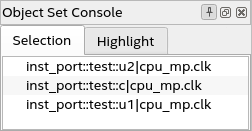
In this mode, all related ports (input/output) are automatically highlighted when you expand an interface and select any port under the interface.
In the following example, you can see that when you expand the cpu_mp interface in c, u1, and u2 modules and select the cpu_mp.clk port in one of the modules, all related ports (highlighted in red) are automatically highlighted, as shown in the following image:
Interface Only Mode
In this mode, only modules with interfaces are shown in the schematic viewer. All non-interface ports and objects are removed. This mode is helpful in viewing the relationship between modules that are connected by an interface. You can expand each interface to view all ports under the interface.
In the following example, you can observe that the non-interface port o[3:0] is removed in c and u1 modules, and all other objects are no longer visible in the schematic viewer.