Intel® Quartus® Prime Pro Edition User Guide: Design Compilation
A newer version of this document is available. Customers should click here to go to the newest version.
2.3.1.7. Filtering Ports and Nets
You access the Filter feature either from the netlist hierarchy browser or the schematic viewer of the RTL Analyzer GUI. Select and right-click on the desired design object (port or node), point to Filter, and select the desired filter command in the context-sensitive menu, as shown in the following image. The RTL Analyzer generates a new page in the schematic view displaying the netlist that remains after filtering.
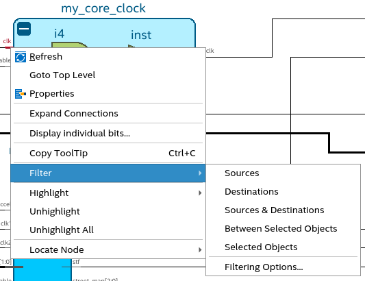
The following filtering commands are available:
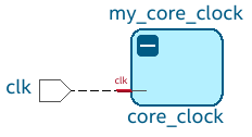
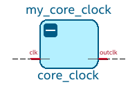
- Sources: Displays only the input source nodes that feed the selected port. In the following example image, when you use the Sources filter for the selected instance port clk, the source port clk displays:
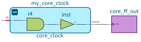
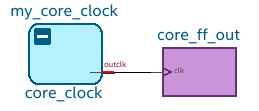
- Destinations: Displays only the fan-out destination nodes fed by the selected port. In the following example image, when you use the Destinations filter for the selected instance port clk, the destination instance port outclk displays:
- Sources & Destinations: This option is a combination of source and destination filtering commands. The filtered view displays both sources and destinations of the selected port. In the following example image, when you use the Sources & Destinations filter for the selected instance port clk, you can view the source and destination nodes:
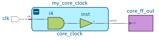
- Between Selected Objects: Displays nodes and connections in the path between the selected ports. In the following image, when you use the Between Selected Objects filter for the selected instance port clk, all objects between the input and output instance ports displays:
- Selected Objects: Displays only the selected objects. In the following image, when you use the Selected Objects filter, only the selected instance ports clk and outclk displays:
For all the filtering commands, the RTL Analyzer stops tracing through the netlist to obtain the filtered netlist when it reaches the port or instances. You can further control the filtering result by selecting Filter > Filtering Options in the context-sensitive menu. The Filtering Options dialog box provides the following filtering options:
- Stop filtering at register (optional): The filtering stops when a register is encountered. This option is turned on by default.
- Stop filtering at design partition (optional): The filtering stops at the design partition. This option is turned on by default.
- A specified number of logic levels: The logic levels are counted from the selected port. The default value is 5 to ensure optimal processing time when performing filtering. However, you can specify a value between 1 and 15.