7.1.4. Recommended Pressure Variation Across the Package
Altera has characterized various thermal interface materials (TIMs) of gap pads using an in-house TIM tester, and obtained curves of resistance vs. pressure. These tests were conducted for various TIMs across different pressure ranges.
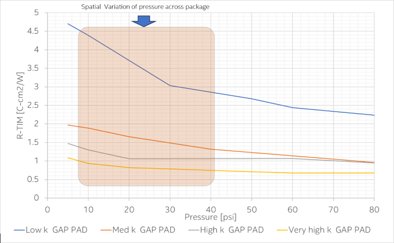
As shown below, the measured curves for initial gap pad thicknesses in the range of 0.8 to 1.2 mm reveal that performance varies based on material composition and manufacturer. These are provided as a best guide for typical low-power FPGA applications. However, the appropriate gap pad thickness and TIM type can be selected based on the gap between the package and heatsink requirements.
As discussed in the previous section, package load limits, die warpage, and thermal solution tolerance cause the attached pressure to vary.
The contact pressure must be maintained in the typical range of 10 to 40 psi. This ensures that it meets both thermal and mechanical loading specification requirements.