1. Introduction to MAX® 10 FPGA B610 Package Thermal Design Guidelines
2. MAX® 10 FPGA B610 Package Mechanical Construction
3. MAX® 10 FPGA B610 Package CTM Construction
4. Quartus Requirements and Power Estimation
5. General FPGA Thermal Design Considerations
6. Thermal Design Process
7. Thermal Solution Mechanical Design
8. Vendor References
9. Document Revision History for the MAX® 10 FPGA B610 Package Thermal Design User Guide
A. Thermal Design Elements
3. MAX® 10 FPGA B610 Package CTM Construction
Compact thermal models (CTMs) are CAD models used in computational fluid dynamics (CFD) tools. These models simplify certain mechanical design features, such as solder bumps, vias, and substrates, to focus on providing accurate thermal analysis results as outlined in this document.
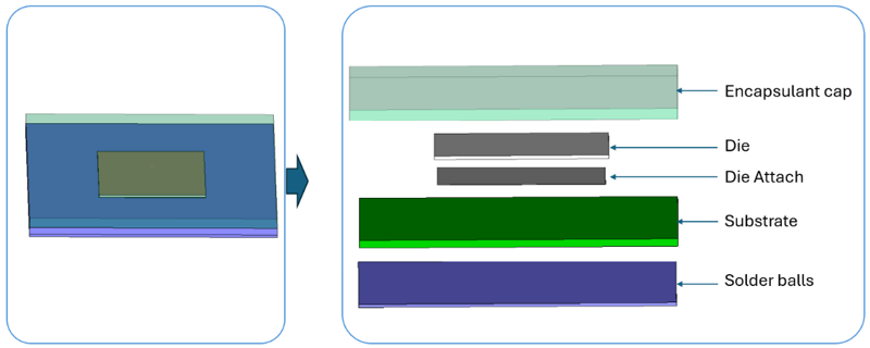
The following figure demonstrates the general structure of the MAX® 10 CTM model. The only input required for the CTM is the package power, and the valid outputs from the CFD analysis are the junction temperature and the heat dissipated from both the top and bottom of the FPGA.
Figure 3. MAX® 10 FPGA B610 Package CTM Construction