1. Introduction to MAX® 10 FPGA B610 Package Thermal Design Guidelines
2. MAX® 10 FPGA B610 Package Mechanical Construction
3. MAX® 10 FPGA B610 Package CTM Construction
4. Quartus Requirements and Power Estimation
5. General FPGA Thermal Design Considerations
6. Thermal Design Process
7. Thermal Solution Mechanical Design
8. Vendor References
9. Document Revision History for the MAX® 10 FPGA B610 Package Thermal Design User Guide
A. Thermal Design Elements
4. Quartus Requirements and Power Estimation
Quartus Power Analyzer (QPA) helps designers to calculate the power of the device based on the input configurations.
Input system thermal parameters into QPA
Because dynamic power is a function of the junction temperature, QPA iteratively calculates the device power for a junction temperature that results from the use-case power and the ambient thermal conditions. Depending on the maturity of the design, it is recommended to use a margin to accommodate changes to the power as the design is modified.
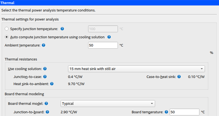
When a given device is loaded into QPA, the QPA Thermal tab automatically loads parameters characteristic to that device. The following are set values for a particular package, and cannot be modified:
- PDYNAMIC V/S TJ curve
- Junction-to-board thermal resistance: ӨJB
- Junction-to-case thermal resistance: ӨJC
- Thermal interface material (TIM) thermal resistance: ӨCS
The following are user inputs that you can specify:
- Ambient temperature: TA
- Cooling solution size and airflow, resulting in ӨSA
- Board thermal model type
- Board temperature: TB
You have the option to change any of the parameters to match your system configuration.
Figure 4. QPA Thermal Tab for Input Parameters