7.2.3. Parametric Studies with Different TIM Materials
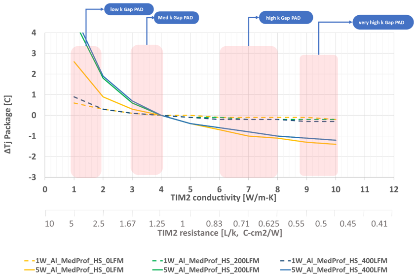
A baseline design was established using packages with heatsinks of different sizes, as shown in the table below. For each heatsink variant, a gap pad TIM with an effective thermal conductivity of 4 W/m-K and a bond line thickness (BLT) of 500µm was considered. This analysis did not account for changes in the spatial performance of TIM2. The following figure illustrates the increase in junction temperature for different designs as TIM conductivity varied from 1 to 10W/m-K, and the package junction temperature compared to the baseline design.
| Heatsink Profile Size | Profile | Flow Condition (Velocity, LFM) |
|---|---|---|
| 19x19x15 mm | Low | 0, 200, 400 |
| 19x19x23 mm | Medium | 0, 200, 400 |
| 19x19x28 mm | High | 0, 200, 400 |
For low-power applications ~1W range the TIM does not play a role, and a low thermal conductivity gap pad is sufficient. For powers in the range of ~5W, using GAP PAD TIMs of medium thermal conductivity from 3 to 4/m-K, significantly enhances thermal performance, which is depicted below for medium profile heatsink. Similar observation holds good for low profile and high profile heatsink types. Beyond this threshold, high-performance TIM materials have only a marginal impact on thermal performance less than 1°C. For these applications, medium conductivity gap pads are typically the preferred choice due to their cost-effectiveness.