4.3. Generating the Design Example
Figure 6. Design Example Generation Procedure
- In the Intel® Quartus® Prime Pro Edition software, create a new project (File → New Project Wizard).
- Specify the Directory Name, and Top-Level Entity.
- For Project Type, accept the default value, Empty project. Click Next.
- For Add Files click Next.
- For Family, Device & Board Settings under Family, select Intel® Agilex™ or Intel® Stratix® 10 .
- If you select Intel® Stratix® 10 in the last step, select Stratix 10 DX in the Device pull-down menu.
- Select the Target Device for your design.
- Click Finish.
- In the IP Catalog locate and add the Intel P-Tile Avalon® -MM IP for PCI Express* .
- In the New IP Variant dialog box, specify a name for your IP. Click Create.
- On the Top-Level Settings and PCIe* Settings tabs, specify the parameters for your IP variation. For example, select Endpoint for the EP variant.
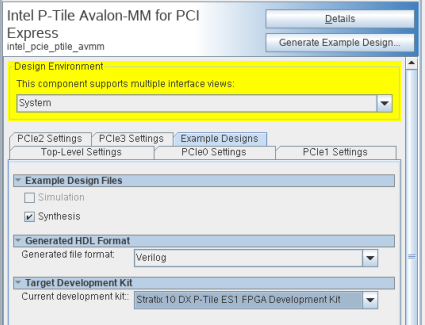
- On the Example Designs tab, make the following selections:
- For Example Design Files, turn on the Synthesis option. If you do not need these synthesis files, leaving the corresponding option turned off significantly reduces the example design generation time.
- For Generated HDL Format, only Verilog is available in the current release.
- For Target Development Kit, select the appropriate option. For the current release, the supported development kits are:
- Intel® Stratix® 10 DX P-Tile ES1 FPGA Development Kit
- Intel® Agilex™ F-Series P-Tile ES0 FPGA Development Kit
- Select Generate Example Design to create a design example that you can compile and download to hardware. If you select one of the P-Tile development boards, the device on that board overwrites the device previously selected in the Intel® Quartus® Prime project if the devices are different. When the prompt asks you to specify the directory for your example design, you can accept the default directory, <project_dir>/intel_pcie_ptile_avmm_0_example_design, or choose another directory.
Figure 7. Example Designs Tab
- Click Finish. You may save your .ip file when prompted, but it is not required to be able to use the example design.
- Open the example design project.
- Compile the example design project to generate the .sof file for the complete example design. This file is what you download to a board to perform hardware verification.
- Close your example design project.
Note: You cannot change the PCIe pin allocations in the Intel® Quartus® Prime project. However, to ease PCB routing, you can take advantage of the lane reversal and polarity inversion features supported by this IP.