4.3.10. Clock Controller
The Clock Controller application sets the Si5391 programmable oscillators to any frequency between 0.16 MHz and 710 MHz.
The Clock Controller application sets the Si5332 programmable oscillators to any frequency between 0.1 MHz and 712.5 MHz.
The Clock Control communicates with the Intel® MAX® 10 on the board through the JTAG bus. The programmable oscillator are connected to the Intel® MAX® 10 device through a 2-wire serial bus.
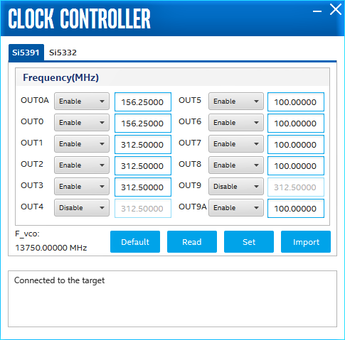
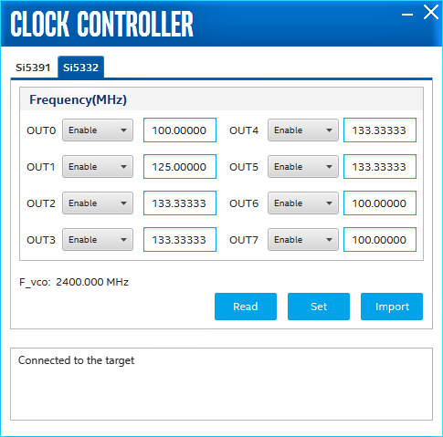
Si5391 tab and Si5332 tab display the same GUI controls for each clock generators. Each tab allows for separate control. The Si5391 is capable of synthesizing four independent user-programmable clock frequencies up to 710 MHz.
The controls of the clock controller are described below:
F_vco
Displays the generating signal value of the voltage-controlled oscillator.
Register
Display the current frequencies for each oscillator.
Frequency
Allows you to specify the frequency of the clock in MHz.
Read
Reads the current frequency setting for the oscillator associated with the active tab.
Default
Sets the frequency for the oscillator associated with the active tab back to its default value. This can also be accomplished by power cycling the board.
Set
Sets the programmable oscillator frequency for the selected clock to the value in the CLK0 to CLK3 controls for the Si5391. Frequency changes might take several milliseconds to take effect. You might see glitches on the clock during this time. Intel recommends resetting the FPGA logic after changing frequencies.
Import
Import register map file generated from Silicon Laboratories ClockBuilder Desktop.