Visible to Intel only — GUID: qij1573492228820
Ixiasoft
Visible to Intel only — GUID: qij1573492228820
Ixiasoft
3.1.4.1. Considerations for Designing DDR4 x72 Interface Together with an AVST x8/x16/x32 Configuration Scheme
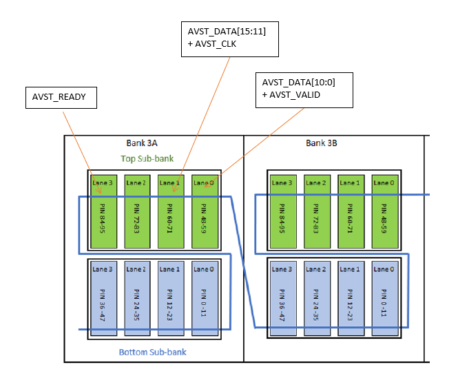
The AVST x8 configuration scheme uses the dedicated SDM I/O pins and does not impact the number of DDR4 x72 interfaces that can be implemented on the device. An AVST x32 configuration scheme uses all four of the I/O lanes in the top sub-bank in Bank 3A. This breaks the contiguity requirement and reduces the maximum number of DDR4 x72 interfaces that can be supported on the device.
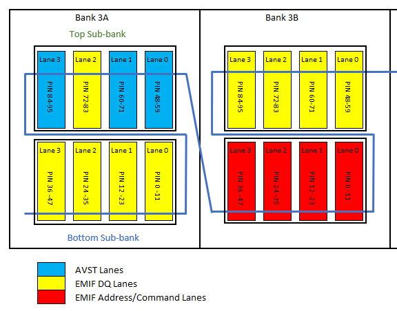
However, the AVST x16 configuration scheme only uses three I/O Lanes. I/O Lane 2 in the top sub-bank in Bank 3A is available for EMIF purposes and maintains the contiguity requirement. This I/O Lane can be used as a DQ Lane for EMIF purposes.

To implement a DDR4 x72 interface using the top sub-bank in Bank 3A together with an AVST x16 configuration scheme, you must use the address/command scheme with four IO Lanes. The following figure shows the I/O lane assignment for implementing a DDR4 x 72 interface in such a scenario.

The following table shows the maximum number of DDR4 x72 interfaces that can be supported with different AVST configuration schemes.
| Device/Package | 1× DDR4 x72 | 2× DDR4 x72 | 3× DDR4 x72 | 4× DDR4 x72 | 6× DDR4 x72 | 8× DDR4 x72 |
|---|---|---|---|---|---|---|
| AGF014/AGF012, R24A/R24B | AVST 8, 16, 32 | AVST 8, 16, 32 | AVST 8, 16, 32 | AVST 8, 16 | N/A | N/A |
| AGF027/AGF022, R24C | AVST 8, 16, 32 | AVST 8, 16, 32 | AVST 8, 16, 32 | AVST 8, 16 | N/A | N/A |
| AGF027/AGF022, R25A | AVST 8, 16, 32 | AVST 8, 16, 32 | N/A | N/A | N/A | N/A |
| AGF027/AGF022, R31C | AVST 8, 16, 32 | AVST 8, 16, 32 | AVST 8, 16, 32 | AVST 8 | N/A | N/A |
| AGI027/AGI022, R29A | AVST 8, 16, 32 | AVST 8, 16, 32 | AVST 8, 16, 32 | AVST 8 | N/A | N/A |
| AGI027/AGI022, R31B | AVST 8, 16, 32 | AVST 8, 16, 32 | AVST 8, 16, 32 | AVST 8 | N/A | N/A |
| AGF019/AGF023, R25A | AVST 8, 16, 32 | AVST 8, 16 | N/A | N/A | N/A | N/A |
| AGF006/AGF008, R16A | AVST 8, 16, 32 | N/A | N/A | N/A | N/A | N/A |
| AGF006/AGF008, R24C | AVST 8, 16, 32 | AVST 8, 16, 32 | N/A | N/A | N/A | N/A |
| AGF012/AGF014, R24C | AVST 8, 16, 32 | AVST 8, 16, 32 | AVST 8, 16, 32 | AVST 8, 16 | N/A | N/A |
| AGF019/AGF023, R24C | AVST 8, 16, 32 | AVST 8, 16 | N/A | N/A | N/A | N/A |
| AGI019/AGI023, R31B | AVST 8, 16, 32 | AVST 8, 16 | N/A | N/A | N/A | N/A |
| AGI019/AGI023, R18A | AVST 8, 16, 32 | AVST 8, 16 | N/A | N/A | N/A | N/A |
| AGI035/AGI040, R39A | AVST 8, 16, 32 | AVST 8, 16, 32 | N/A | N/A | N/A | N/A |
| AGI019/AGI023, R31C | AVST 8, 16, 32 | AVST 8, 16 | N/A | N/A | N/A | N/A |
| AGI027, R29B | AVST 8, 16, 32 | AVST 8, 16, 32 | AVST 8, 16, 32 | AVST 8 | N/A | N/A |
| AGI041, R29D | AVST 8, 16, 32 | AVST 8, 16, 32 | AVST 8, 16, 32 | AVST 8 | N/A | N/A |
| Device/Package | 1× DDR4 x72 | 2× DDR4 x72 | 3× DDR4 x72 | 4× DDR4 x72 | 6× DDR4 x72 | 8× DDR4 x72 |
|---|---|---|---|---|---|---|
| AGF014/AGF012, R24A/R24B | AVST 8, 16, 32 | AVST 8, 16, 32 | AVST 8, 16, 32 | AVST 8 | N/A | N/A |
| AGF027/AGF022, R24C | AVST 8, 16, 32 | AVST 8, 16, 32 | AVST 8, 16, 32 | AVST 8 | N/A | N/A |
| AGF027/AGF022, R25A | AVST 8, 16, 32 | AVST 8, 16, 32 | AVST 8, 16, 32 | AVST 8, 16, 32 | N/A | N/A |
| AGF027/AGF022, R31C | AVST 8, 16, 32 | AVST 8, 16, 32 | AVST 8, 16, 32 | AVST 8 | N/A | N/A |
| AGI027/AGI022, R29A | AVST 8, 16, 32 | AVST 8, 16, 32 | AVST 8, 16, 32 | AVST 8 | N/A | N/A |
| AGI027/AGI022, R31B | AVST 8, 16, 32 | AVST 8, 16, 32 | AVST 8, 16, 32 | AVST 8 | N/A | N/A |
| AGF019/AGF023, R25A | AVST 8, 16, 32 | AVST 8, 16, 32 | AVST 8, 16, 32 | N/A | N/A | N/A |
| AGF006/AGF008, R16A | AVST 8, 16, 32 | AVST 8, 16, 32 | N/A | N/A | N/A | N/A |
| AGF006/AGF008, R24C | AVST 8, 16, 32 | AVST 8, 16, 32 | AVST 8, 16, 32 | AVST 8 | N/A | N/A |
| AGF012/AGF014, R24C | AVST 8, 16, 32 | AVST 8, 16, 32 | AVST 8, 16, 32 | AVST 8, 16, 32 | N/A | N/A |
| AGF019/AGF023, R24C | AVST 8, 16, 32 | AVST 8, 16, 32 | AVST 8, 16, 32 | N/A | N/A | N/A |
| AGI019/AGI023, R31B | AVST 8, 16, 32 | AVST 8, 16, 32 | AVST 8, 16, 32 | N/A | N/A | N/A |
| AGI019/AGI023, R18A | AVST 8, 16, 32 | AVST 8, 16, 32 | AVST 8, 16, 32 | N/A | N/A | N/A |
| AGI035/AGI040, R39A | AVST 8, 16, 32 | AVST 8, 16, 32 | AVST 8, 16, 32 | AVST 8 | N/A | N/A |
| AGI019/AGI023, R31C | AVST 8, 16, 32 | AVST 8, 16, 32 | AVST 8, 16, 32 | N/A | N/A | N/A |
| AGI027, R29B | AVST 8, 16, 32 | AVST 8, 16, 32 | AVST 8, 16, 32 | AVST 8 | N/A | N/A |
| AGI041, R29D | AVST 8, 16, 32 | AVST 8, 16, 32 | AVST 8, 16, 32 | AVST 8 | N/A | N/A |
Restriction for using JB26, JH26, JP26 and JL27 on AGI041, Package R29D
You must adhere to these guidelines when using pin JB26, JH26, JP26 and JL27 on AGI041, package R29D, to reduce crosstalk coupling from adjacent I/O pins (JP26 and JL27) to R-tile REFCLK pins (JB26 and JH26).

Follow these guidelines:
- Implement one of the 3 layout options shown in the above figure.
- Route DDR/IO (JP26, JL27) at deep layer, L16 and R-tile REFCLK at shallow layer, L3. This is only applicable to pin JB26, JH26, JP26 and JL27.
- Keep maximum R-tile REFCLK route length < 3.7 inches.
- Refer to routing recommendations for REFCLK generator from manufacturer (if applicable).
- Keep at least 5xH separation between 100MHz R-tile REFCLK to DDR4/other GPIO signals.
Figure 48. Separation between R-Tile REFCLK to DDR4/GPIO signals
 Note: H is the closest distance measuring from trace to ground reference plane in Z-direction.