3.1.4.5. AN and LT Status
The AN and LT features are supported for example and your custom designs in Quartus® Prime Pro Edition software version 23.3 onwards.
Note: Serial loopback is not supported for AN/LT with FHT PMA.
To enable AN and LT along with Ethernet IP, select the Enable auto-negotiation and link training checkbox in the Ethernet Hard IP GUI.
To enable the Ethernet Toolkit for your custom design, you must enable the Enable AN/LT Debug Endpoint for Ethernet toolkit checkbox in the F-Tile Auto-Negotiation and Link Training for Ethernet Intel FPGA IP GUI as shown in the following figure.
Figure 25. Enable Ethernet Toolkit for F-Tile Auto-Negotiation and Link Training for Ethernet Intel FPGA IP
The Ethernet Toolkit displays AN/LT status in the IP Configuration and Other Information tab as shown in the figure below.
Figure 26. IP Configuration and Other Information Tab

A new sub tab named AN/LT Status is added at the bottom of the Status tab displaying AN/LT features.
Figure 27. Status Tab for Ethernet Toolkit and AN/LT Status Sub Tab
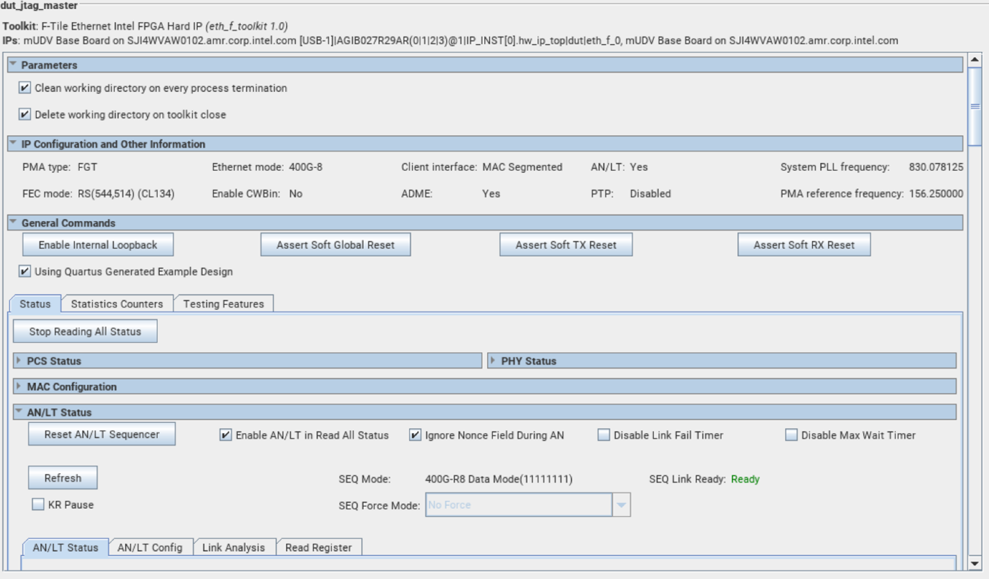
The AN/LT Status section shown above contains a number of checkboxes as listed below.
- Reset AN/LT Sequencer—Resets the AN/LT sequencer.
- Ignore Nonce Field During AN—Needs to be selected when the F-tile is connected in loopback mode.
- Disable Link Fail Timer—Disables the Link Fail Timer when selected.
- Disable Max Wait Timer—Disables the Max Wait Timer when selected.
- Refresh—Updates all the registers data when pressed.
- KR Pause—Pauses the KR CPU when selected.
- SEQ Force Mode—Not supported in the current Release.
The AN/LT Status tab contains 4 different tabs:
- AN/LT Status—Displays the register status information of both AN and LT, which includes the following:
- LT Status Per Lane (if design supports multi lanes)
- LP Base Page details
- LP Next Page details
- Information about the value of a few AN/ LT status registers
Figure 28. AN/LT Status Tab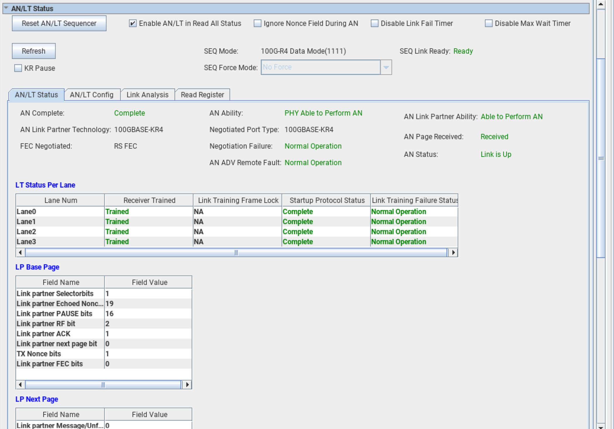
- AN/LT Config—This sub tab includes AN and LT configuration registers. which the user can enable or disable.
- Enable AN—Enables AN when selected; disables AN when unselected.
- AN Enabled—Displays whether AN is enabled or not.
- Enable LT—Enables LT when selected; disables LT when unselected.
- LT Enabled—Displays whether LT is enabled or not.
- Reset AN—Resets all state machines.
Figure 29. AN/LT Config Tab
- Link Analysis—This sub tab is used for Link Analysis. It takes a csv file with Signal Tap data as an input and displays the time delta for different KR/AN/LT states.
- You must tap the kr_debug_0 signal for the AN/LT instances and ports from the signal tap analyzer tool.
- Convert the .STP file data into the csv format and save it into a file.
- You must upload the converted csv file into the tool and click the Start Analysis button.
- If the tool does not find the kr_debug_0 signal data from the csv file, then it displays the error Required Signals Not Found.
- Based on data in the csv file, the tool calculates the number of samples captured (iterations of AN/LT sequence) for each port and AN/LT instance.
- You can check the data for each sample by selecting the AN/LT instance, port instance, and the sample (iteration) number from the dropdown menu options. You must press the Display Sample button after selecting from the dropdown list.
- The tool shows the data for Auto negotiation states, Link training states, and Data mode states.
Figure 30. Link Analysis Tab - Read Register—This sub tab is used to dump all available register data into a csv file.
- It reads the data from the board when users click on Press to Export Reg Data.
- The tool captures dynamic data.
- The csv file includes the Register Name, Bit Name, Bit Value, and Description of the Bit columns.
- Users must provide a csv file as an input into which data can be dumped.
Figure 31. Read Register Tab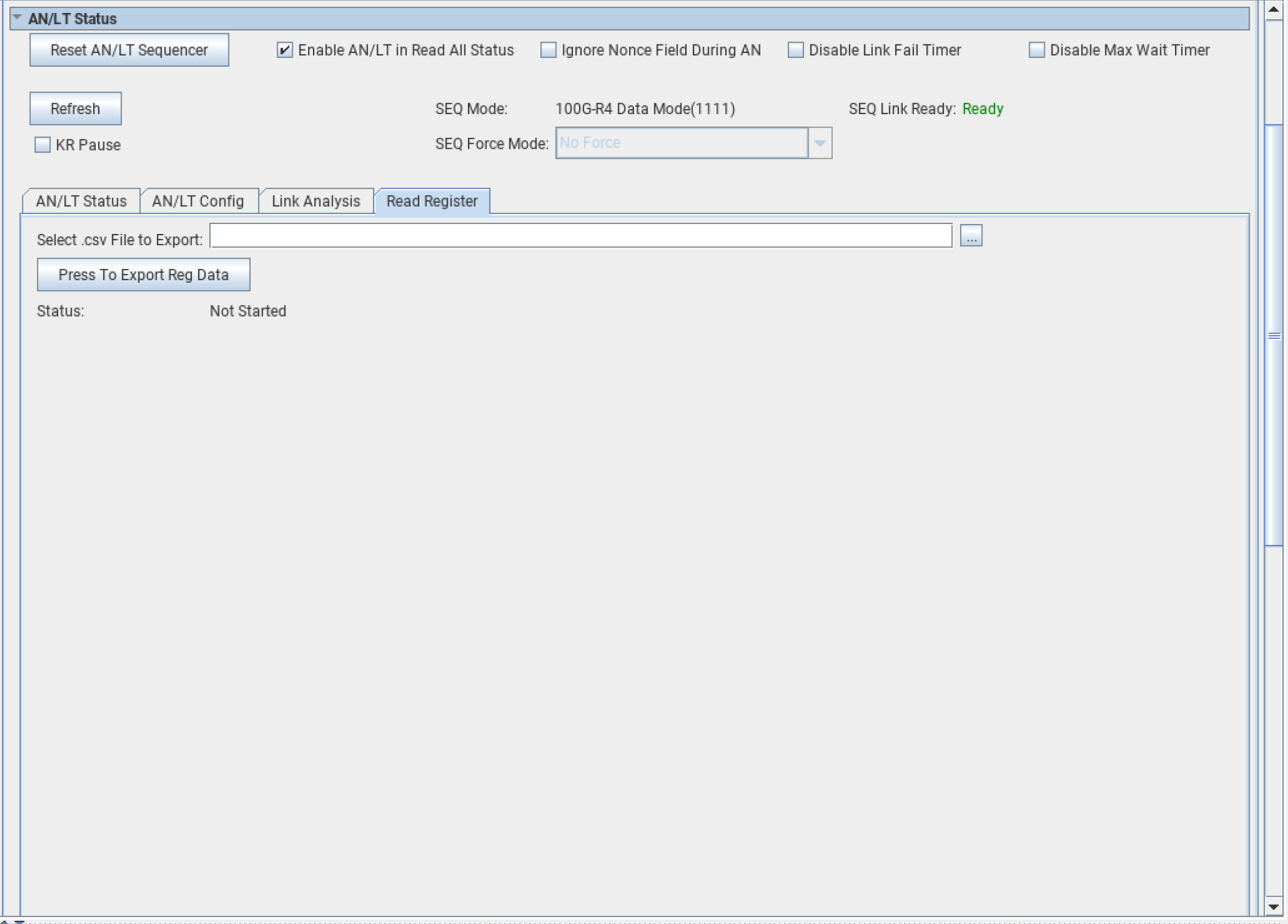
| Register Name | Field Name | Field Value | Field Description |
|---|---|---|---|
| seq_cfg | kr_pause | 0 |
Pauses AN/LT function
Set this bit before accessing PMA registers via the transceiver reconfig interface to ensure no conflict with the AN/LT function. Also, you must set this bit (kr_pause) before starting the PRBS generator in the Transceiver Toolkit (TTK). |