4.3.8. Clock Controller
The Clock Controller application sets the Si5332 programmable oscillators to any frequency between 5 MHz and 312.5 MHz differential.
The Clock Controller application sets the Si570 programmable oscillators to any frequency between 10 MHz and 725 MHz.
You can start using the Clock Controller feature by selecting the Clock icon on the BTS GUI.
The Clock Controller communicates with the MAX® 10 on the board through the JTAG bus. The programmable oscillator are connected to the MAX® 10 device through a 2-wire serial bus.
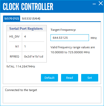
Serial Port Registers
Shows the current values from the Si570 registers for frequency configuration.
Target Frequency (MHz)
Allows you to specify the frequency of the clock. Legal values are between 10 MHz and 725 MHz with eight digits of precision to the right of the decimal point. For example, 421.31259873 is possible within 100 parts per million (ppm). The Target Frequency control works in conjunction with the Set control.
fXTAL
Shows the calculated internal fixed-frequency crystal based on the serial port register values.
Default
Sets the frequency for the oscillator associated with the active tab back to its default value. This can also be accomplished by power cycling the board.
Set
Sets the programmable oscillator frequency for the selected clock to the value in the Target Frequency control for the programmable oscillators. Frequency changes might take several milliseconds to take effect. You might see glitches on the clock during this period. Altera recommends resetting the FPGA logic after changing frequencies.
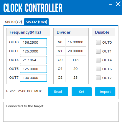
Si5332 tab displays the same GUI controls for each clock generators. The Si5332 is a high-performance, low-jitter clock generator capable of synthesizing five independent banks for user-programmable clock frequencies up to 312.5 MHz.
The controls of the clock controller are described below:
F_vco
Displays the generating signal value of the voltage-controlled oscillator.
Frequency
Allows you to specify the frequency of the clock MHz.
Divider
Display the divider mode and value currently being used on this board.
Disable
Allows you to disable a single output.
Read
Reads the current frequency setting for the oscillator.
Set
Sets the programmable oscillator frequency for the selected clock to the value in OUT0, OUT1, OUT4, OUT6 and OUT7 controls for the Si5332. Frequency changes might take several milliseconds to take effect. You might see glitches on the clock during this period. Altera recommends resetting the FPGA logic after changing frequencies.
Import
Import register map file generated from the Skyworks* Clockbuilder Pro tool.