5.1. Power Guidelines
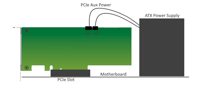
In a standard PCIe* compliant system
In this mode, plug the board into an available PCI Express* slot and connect the standard 2x4 and 2x3 auxiliary power cords available from the PC's ATX power supply to the respective mating connectors on the board (J26 and J27). The PCIe* slot together with the two auxiliary PCIe* power cords are required to power the entire board. If you do not connect the 2x4 or 2x3 auxiliary power connections, it prevent the board from powering on. The power switch SW7 is ignored when the board is used in the PCIe* system.
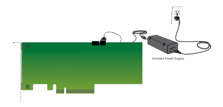
As a stand-alone evaluation board powered by included power supply
In this mode, plug the included power supply into the 2x3 pin connector (J27) and the AC power cord of the power supply into a power outlet. This power supply will provide the entire power to the board without the need to obtain power from the PCIe* slot or the 2x4 power connector (J26). The power switch SW7 controls powering the board on/off.