A newer version of this document is available. Customers should click here to go to the newest version.
4.3.10. Different Input and Output Width
The DCFIFO_MIXED_WIDTHS function supports different write input data and read output data widths if the width ratio is valid. The FIFO parameter editor prompts an error message if the combinations of the input and the output data widths produce an invalid ratio. The supported width ratio in a power of 2 and depends on the RAM.
The IP core supports a wide write port with a narrow read port, and vice versa. The current supported mixed width ratios for Agilex™ 7 devices are listed in the following table:
| Device Family | Valid Width Ratio |
|---|---|
| Agilex™ 7 | 1, 2, 4, 8, 16, and 32 |

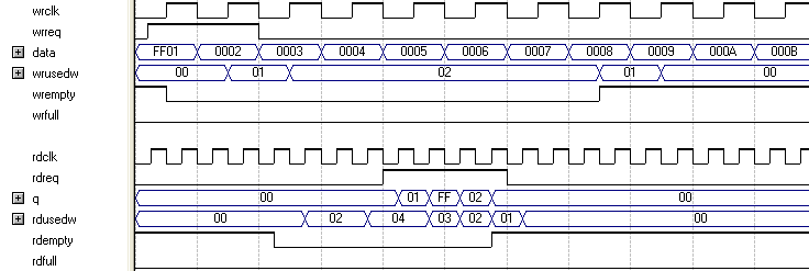
In this example, the read port is operating at twice the frequency of the write port. Writing two 16-bit words to the FIFO buffer increases the wrusedw flag to two and the rusedw flag to four. Four 8-bit read operations empty the FIFO buffer. The read begins with the least-significant 8 bits from the 16-bit word written followed by the most-significant 8 bits.

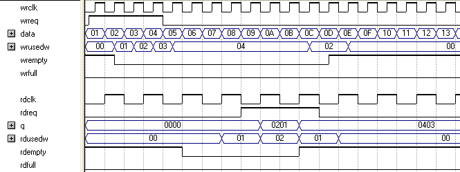
In this example, the read port is operating at half the frequency of the write port. Writing four 8-bit words to the FIFO buffer increases the wrusedw flag to four and the rusedw flag to two. Two 16-bit read operations empty the FIFO. The first and second 8-bit word written are equivalent to the LSB and MSB of the 16-bit output words, respectively. The rdempty signal stays asserted until enough words are written on the narrow write port to fill an entire word on the wide read port.