AN 750: Using the Altera PDN Tool to Optimize Your Power Delivery Network Design
1.6.7. Move Decoupling Capacitors to the Top Surface of the PCB
In all steps so far, the decoupling capacitors are placed on the bottom surface of the PCB and the FPGA is placed on the top.
Traditionally the decoupling capacitors are placed at the bottom side of the PCB, beneath the FPGA and connect directly to the BGA vias. It is assumed that the best electrical position is the closest physical location to the FPGA pins.
In the layer-stack if the power and ground plane pair are close to the FPGA, the total vertical inductance of the vias between the capacitors and plane, and between the plane and FPGA is less if the decoupling capacitors are placed on the top surface of the PCB.
Assuming wide contiguous power and ground planes that have thin separation, the inductance is much lower even though the physical horizontal distance of the capacitors placed around the outside of the FPGA is far greater.
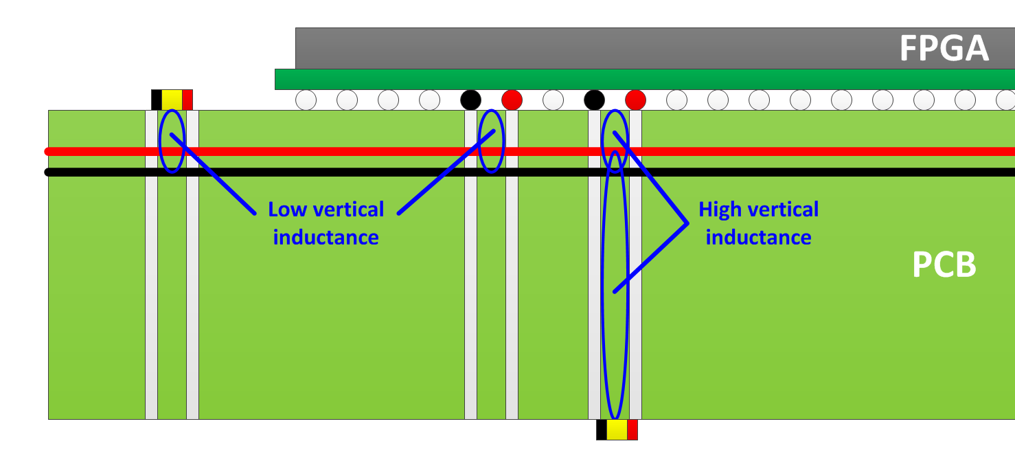
In this 18 Layer example, the VCCT_GXB, and VCCR_GXB supplies are allocated to layer 4 which is closer to the FPGA than the mid point in the layer-stack. Therefore if the capacitors are placed on the top surface of the PCB, the combined vertical loop inductance between decoupling capacitor to plane, and plane to FPGA is lower.
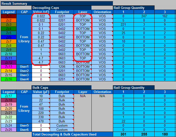
Providing the PDN Tool with the freedom to place capacitors on either the top or bottom surface of the PCB can be achieved by duplicating entries for select capacitor values. You can allocate one to the top surface, and the other to the bottom surface. This is shown below with the effect that the number of capacitors required for the VCCT_GXB, and VCCR_GXB supplies is reduced to 255 and 180 respectively.
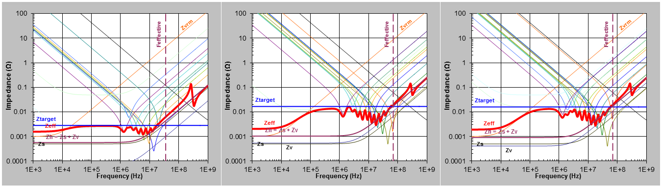
The target impedance is now met up to 70MHz for the VCCT_GXB, and VCCR_GXB supplies but the large number of high-frequency 22nF capacitors shows there are still challenges in achieving Ztarget at high-frequencies.