AN 787: Intel® Stratix® 10 Thermal Modeling and Management with the Early Power Estimator
1.10. Early Power Estimator (EPE)
Use the EPE tool to estimate the power dissipation of the dies in an Intel® Stratix® 10 FPGA. An Excel spreadsheet provides the interface to the tool, and it contains multiple worksheets, each applicable to a part of the design. The EPE tool calculates thermal design parameters that are unique to each design. To activate the Thermal worksheet of the EPE, the following parameters need to be modified in the Main worksheet of the EPE:
- Set the Power Characteristics to Maximum.
- Set the Junction Temp Mode to Detailed Thermal Model.
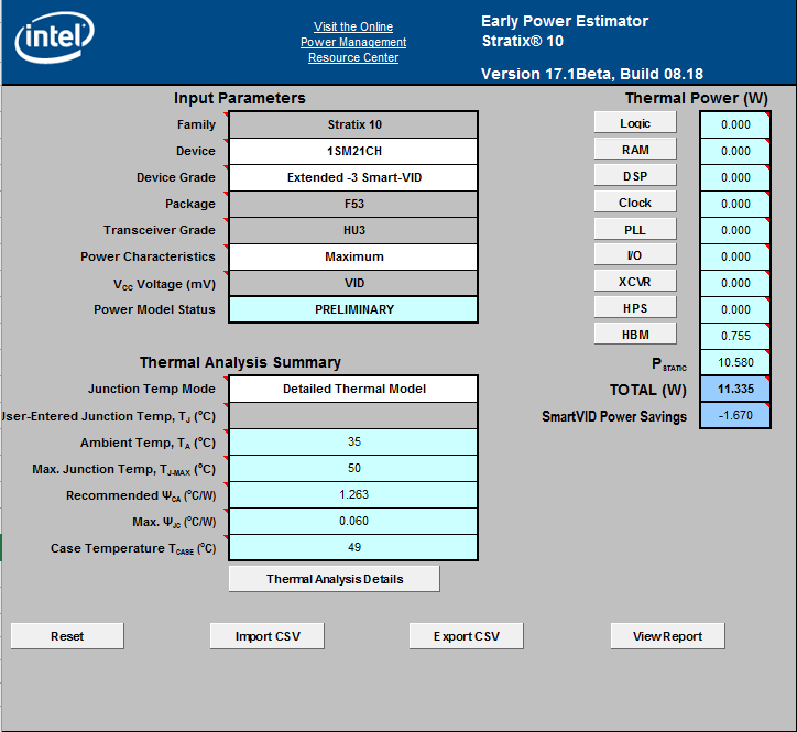
This activates the Thermal worksheet of the EPE tool, and as a result, any changes made to the EPE affect the values in this worksheet. To obtain the correct thermal values for the analysis, you must enter all the necessary design information and settings in the subsequent worksheets of the EPE.
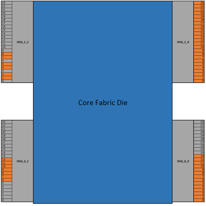
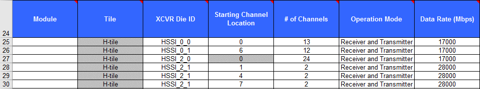
Selecting the device, package, and transceiver in the Main worksheet of EPE will enable selection of appropriate transceiver and HBM die types and counts in XCVR and HBM worksheets. In the XCVR worksheet you must specify placement of each transceiver in the exact tile and channel location (0-23) to be used in the design. This is necessary to obtain the correct power and thermal parameters. Similarly, in the HBM worksheet you must select the correct HBM and channel numbers (0-7) for your application.
For an example of transceiver placement refer to Figure 7 showing an Intel® Stratix® 10 device with 4 H-Tiles configured to use 54 transceiver channels placed in specific channel locations.
After you have entered all the design data and activated the Thermal worksheet, set the proper thermal variables in the Thermal worksheet .
- Apply Recommended Margin: Intel® recommends that you turn on the recommended margin to ensure sufficient cooling and account for approximations in power modeling.
- Ambient Temp, T A (°C): Temperature of the air or other coolant that flows over the heat sink.
- Max. Junction Temp, T J-MAX (°C): Allowed maximum temperature of any die in the package, regardless of its type. The Max TJ setting can be set to any value that a design requires below the max rating of device.
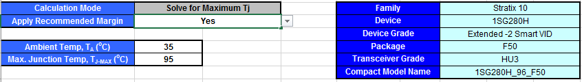
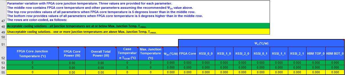
Once you have entered the thermal settings, the EPE updates the power dissipation of all dies based on the required thermal solution. For example, if the maximum allowed junction temperature is 95°C, the EPE calculates a cooling solution that satisfies this requirement. That is, at least one die is operating at 95°C, while other dies are operating at lower temperatures due to their lower power consumption or power density.
The EPE also provides a solution table which consists of three rows and depicts three sets of solutions. The middle row (Operating Point) is the same as the above solution, and the other two rows represent solutions that are 5°C above and below the core operating temperature resulting from the design. Using this table, you can create the temperature dependent core die power curve which is used in the CFD modeling.