AN 787: Intel® Stratix® 10 Thermal Modeling and Management with the Early Power Estimator
1.6. Intel® Stratix® 10 FPGA Thermal Design Parameters
The Intel® Stratix® 10 FPGA thermal parameters do not contain the traditional θJC and θJB values due to its MCM construction. Therefore, you cannot use the two resistor models for the thermal modeling of the package. Intel® offers a Compact Thermal Model (CTM) which will be discussed in the next section. You will need a combination of CTM and the following thermal parameters for the thermal engineering of an Intel® Stratix® 10 device.
| Parameter | Description |
|---|---|
| TA | Ambient temperature, measured locally surrounding the FPGA. Measure the ambient temperature just upstream of a passive heat sink or at the fan inlet for an active heat sink. This value affects the junction temperature of the main FPGA core fabric die and its power dissipation. |
| TJ-MAX | TJ-MAX is the maximum junction temperature value that the design allows for the given TA. For example, a design may allow the device maximum rated junction temperature at its maximum TA, but for a lower ambient temperature, the junction temperature requirements may be lower than the maximum rated value. These two cases require two sets of thermal entries to the EPE tool to determine the design parameters. |
| TCORE | Core fabric die temperature. EPE tool evaluates the thermal design parameters over a range of TCORE values. |
| Power | EPE tool reports the power dissipation of each die individually. |
| TTDP | Total Thermal Design Power is the total power dissipation of the device, EPE tool reports TTDP for each main FPGA core fabric die temperature. |
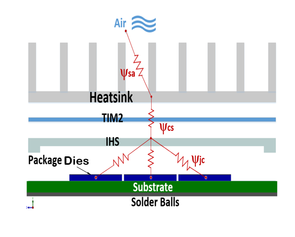
| ΨJC | ΨJC is the thermal resistance between each of the dies in the package and the center of the package IHS. An MCM like the Intel® Stratix® 10 device will have as many ΨJC values as the number of dies in the package. For example, if an Intel® Stratix® 10 contains five dies, there will be five ΨJC values reported by the EPE tool. However, the focus of thermal design is always on the die with maximum ΨJC and that is the one that is used for calculating the TJ-MAX. The ΨJC value is calculated from the following equation: ΨJC = (TJ - TCASE) / TTDP |
| ΨCA | ΨCA is the other thermal resistance value reported by the EPE tool. It is the thermal resistance between the center of the package IHS and ambient temperature. ΨCA can be used as a figure of merit in assessment of the required cooling solution for a design. For example, the lower the ΨCA value, the more aggressive cooling solution is needed. The value of ΨCA is calculated from the following equation: ΨCA = (TCASE - TA) / TTDP |
| TCASE | Integrated heat spreader or case temperature is the temperature at the top center of IHS. If the cooling solution maintains a TCASE equal to the TCASE value reported by the EPE tool, then the TJ-MAX value will be same as entered in the tool. A higher TCASE points to a higher TJ than TJ-MAX. Therefore, the goal of the cooling design should be to keep the TCASE at or below the value reported by the EPE tool. |
Figure 3. Individual Die Thermal Resistance to the Top of IHS
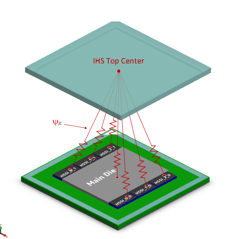
Figure 4. Thermal ResistanceThe diagram shows the thermal resistance from each die to the IHS top surface and also to the air.