AN 787: Intel® Stratix® 10 Thermal Modeling and Management with the Early Power Estimator
ID
683083
Date
7/16/2021
Public
1.1. List of Abbreviations
1.2. Introduction
1.3. Intel® Stratix® 10 Early Power Estimator Tool (EPE)
1.4. Intel® Stratix® 10 FPGA Package Physical Design
1.5. Physical Package Structure
1.6. Intel® Stratix® 10 FPGA Thermal Design Parameters
1.7. Intel® Stratix® 10 Compact Thermal Model (CTM)
1.8. Intel® Stratix® 10 Temperature Sensing Diodes (TSD)
1.9. Intel® Stratix® 10 Thermal Design Process
1.10. Early Power Estimator (EPE)
1.11. Transceiver Channel Spreading
1.12. Thermal Parameter Dependencies
1.13. Intel® Stratix® 10 Thermal Design Example
1.14. Document Revision History for AN 787: Intel® Stratix® 10 Thermal Modeling and Management with the Early Power Estimator
1.13.1. CFD Analysis Setup
The next step in the thermal analysis process is to create a CFD model of the system using the required CTM as shown in row 9 of Thermal worksheet. In the CFD setup, the power dissipation of transceivers and HBMs are set as fixed values and the power dissipation of the core as a temperature-dependent value from the first two columns of the solution table (see the "EPE Thermal Worksheet Solution Table").
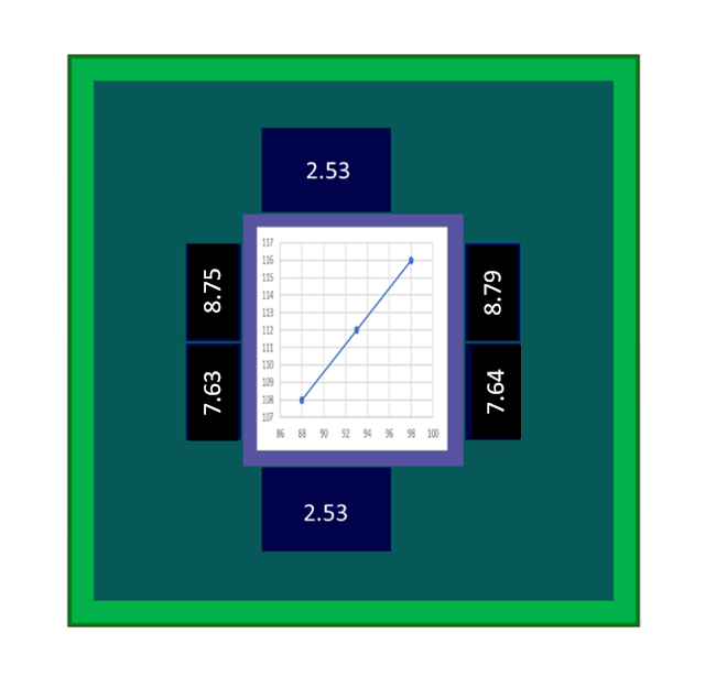
Figure 17. Die Power Assignment for the CFD ModelThis figure shows the FPGA power dissipation assignment to be used in the CFD analysis.
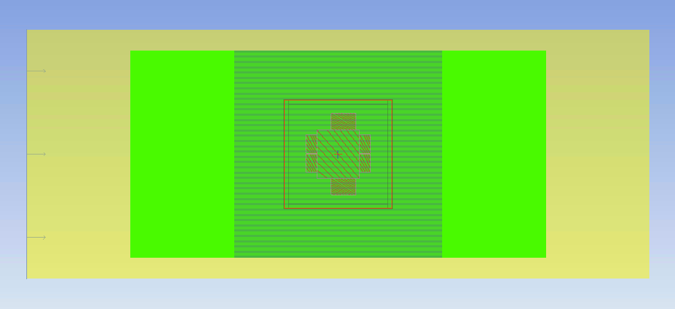
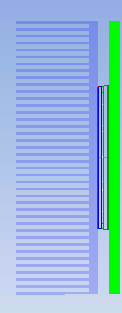
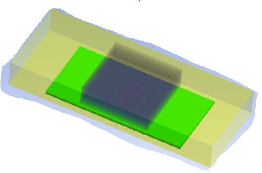
The CFD set up for this example is shown below. FPGA is set in 120 x 35 mm duct with an airflow of 21 CFM. The extruded aluminum heat sink dimensions are: 100 x 100 x 30 mm 40 1x27 mm fins. Air temperature entering the duct is 35 °C.
Figure 18. CFD Set Up
Related Information