LVDS SERDES Transmitter / Receiver IP Cores User Guide
1.5.4.3. Receiver Skew Margin and Transmitter Channel-to-Channel Skew
Changes in system environment, such as temperature, media (cable, connector, or PCB), and loading, affect the receiver's setup and hold times; internal skew affects the sampling ability of the receiver.
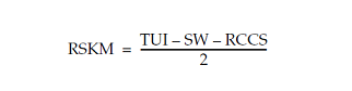
In non-DPA mode, use receiver skew margin (RKSM), receiver channel-to-channel skew (RCCS), and sampling window (SW) specifications to analyze the timing for high-speed source-synchronous differential signals in the receiver data path. The following equation shows the relationship between RSKM, RCCS, and SW.
Where:
- RSKM—is the timing margin between the receiver's clock input and the data input SW.
- Time unit interval (TUI)—is the time period of the serial data (1/fMAX). Also known as the LVDS period in the TimeQuest Timing Analyzer section in the Intel® Quartus® Prime Compilation Report.
- SW—is the period of time that the input data must be stable to ensure that data is successfully sampled by the LVDS receiver. The SW is a device property and varies with device speed grade.
- RCCS— is the timing difference between the fastest and slowest input transitions, including tCO variations and clock skew. Specify RCCS by applying minimum and maximum set_input_delay constraints to the receiver inputs, where RCCS is the difference between the maximum and minimum value.
To obtain accurate RSKM results in the TimeQuest analyzer, specify your RCCS figure using set_input_delay constraints.
The difference between your set_input_delay -min and set_input_delay -max must match your RCCS figure.
For example, to specify an RCCS figure of 0.3 ns:
|
The TimeQuest analyzer takes the 0.3 ns RCCS figure into account during RSKM analysis.
The following figure shows the relationship between the RSKM, RCCS, and SW.
You must calculate the RSKM value to decide whether you can properly sample the data by the LVDS receiver with the given data rate and device. A positive RSKM value indicates the LVDS receiver can properly sample the data; a negative RSKM value indicates the receiver cannot properly sample the data.
The following example shows the RSKM calculation.
| Data Rate: 1 Gbps, Board channel-to-channel skew = 200 ps For Stratix IV devices: RCCS = 100 ps (pending characterization) SW = 300 ps (pending characterization) TUI = 1000 ps Total RCCS = RCCS + Board channel-to-channel skew= 100 ps + 200 ps = 300 ps RSKM= TUI - SW - RCCS = 1000 ps - 300 ps - 300 ps = 400 ps > 0 Because the RSKM > 0 ps, receiver non-DPA mode must work correctly. |