5.3.1.2. IP Parameter Configuration
You can configure the following parameters in the Nios® V/g processor:
- CPU Architecture— Nios® V/g supports FPU as a built-in feature. No functional difference compared to Custom Instruction FPH1 or FPH2. Optionally, you can apply the following configurations:
- Apply branch prediction for better performance.
- Assign the Hart ID register value (mhartid).
- Debug and Use Reset Request—Exposes the debug and reset request interface. Depending on your requirement,you can enable these optional interfaces.
- Lockstep — Enable Nios® V processor Lockstep feature for functional safety-critical applications.
- Reset Agent and Reset Offset—Configures the processor reset vector, equivalent to Reset Vector and Reset Offset in Nios® II/f processor.
- Enable Core Level Interrupt Controller—Enable or disable the CLIC to support pre-emption and configurable interrupt trigger condition.
- Interrupt Mode—Supports Direct Interrupt and Vectored Interrupt and CLIC Interrupt (when Enable Core Level Interrupt Controller is enabled).
- Shadow Register Files—Enable shadow register to reduce the processor’s context switching duration upon interrupt.
- Caches—Enable or disable the caches based on your design preference.
- If you enable the cache, a minimum of 1 Kbyte of cache is instantiated for both data and instruction lines.
- To disable the cache, set it to No Cache.
- Peripheral Regions—Assign these regions to achieve non-cacheable transactions with peripherals, to bypass the caches.
Note: You must place all peripherals within the peripheral region for correct system operation.
- Tightly Coupled Memories— Nios® V/g processor supports up to 4 built-in TCMs, accessible by other host via AXI4-Lite. Nios II/f has 8 TCMs (4 instruction and 4 data) ports that need to be connected to on-chip memory.
- ECC— Nios® V/g processor supports ECC error detection, status reporting, and single bit correction on embedded memory blocks within the core.
- Custom Instructions—Use the Hardware Interface Table and Software CMacro Table to instantiate the custom instruction.
Figure 31. Nios® V/g General Purpose Processor – IP Parameter Editor (Part 1)
Figure 32. Nios® V/g General Purpose Processor – IP Parameter Editor (Part 2) with Enable Core Level Interrupt Controller Turned Off
Figure 33. Nios® V/g General Purpose Processor – IP Parameter Editor (Part 2) with Enable Core Level Interrupt Controller Turned On
Figure 34. Nios® V/g General Purpose Processor – IP Parameter Editor (Part 3)
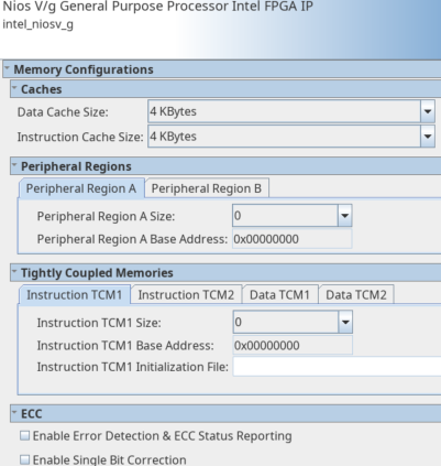
Figure 35. Nios® V/g General Purpose Processor – IP Parameter Editor (Part 4)
| IP Parameter Editor | Nios® V/g General Purpose Processor | Nios® II/f Processor |
|---|---|---|
| Reset Vector | Navigate to Traps, Exceptions, and Interrupts > Reset Vectors | Navigate to Vector > Reset Vector |
| Exception Vector | Define as .exceptions in BSP Editor > Linker Section Mappings. | Navigate to Vector > Exception Vector |
| Fast TLB Miss Exception Vector | — | Navigate to Vector > Fast TLB Miss Exception Vector |
| Instruction Cache | Navigate to Caches > Instruction Cache Size | Navigate to Caches and Memory Interfaces > Instruction Cache |
| Flash Accelerator | — | Navigate to Caches and Memory Interfaces > Flash Accelerator |
| Data Cache | Navigate to Caches > Data Cache Size | Navigate to Caches and Memory Interfaces > Data Cache |
| Tightly-Coupled Memory | Navigate to Tightly Coupled Memories | Navigate to Caches and Memory Interfaces > Tightly-coupled Memory |
| Peripheral Region | Navigate to Peripheral Regions | Navigate to Caches and Memory Interfaces > Peripheral Region |
| Arithmetic Instructions | Built-in multiply and divide instructions | Navigate to Arithmetic Instructions |
| MMU and MPU Settings | — | Navigate to MMU and MPU Settings |
| JTAG Debug | Navigate to Debug > Enable Debug | Navigate to JTAG Debug > JTAG Debug Settings |
| Enable Reset from Debug Module | Navigate to Debug > Enable Reset from Debug Module | Enable when JTAG Debug is enabled. |
| ECC | Navigate to ECC | Navigate to Advanced Features > General > ECC Present |
| Non-vectored Interrupt Controller | Navigate to Traps, Exceptions, and Interrupts > Interrupt Mode > Direct | Navigate to Advanced Features > Interrupt controller > Internal |
| Vectored Interrupt Controller | Navigate to Traps, Exceptions, and Interrupts > Interrupt Mode > Vectored | Navigate to Advanced Features > Interrupt controller > EIC |
| Interrupt Controller with Pre-emption | Navigate to Traps, Exceptions, and Interrupts
|
Navigate to Advanced Features > Interrupt controller > EIC |
| Interrupt Controller with Configurable Trigger Condition | Navigate to Traps, Exceptions, and Interrupts
|
— |
| Shadow Register | Navigate to Traps, Exceptions, and Interrupts > Shadow Register Files | Navigate to Advanced Features > Number of shadow register sets |
| CPU Reset Request | Navigate to Use Reset Request | Navigate to Advanced Features > General > Include cpu_resetrequest and cpu_resettaken signals |
| CPUID Value | Navigate to CPU Architecture > mhartid CSR value | Navigate to Advanced Features > General > CPUID control register value |
| Generate Trace File | — | Navigate to Advanced Features > General > Generate trace file during RTL simulation |
| Exception Checking | Enabled by default | Navigate to Advanced Features > Exception Checking |
| Branch Prediction | Navigate to CPU Architecture > Enable Branch Prediction | Navigate to Advanced Features > Branch Prediction |
| RAM Memory Protection | — | Navigate to Advanced Features > RAM Memory Protection |
| Floating-Point Unit | Navigate to CPU Architecture > Enable Floating Point Unit | — |
| Custom Instructions | Navigate to Custom Instruction | — |
| Disable FSQRT and FDIV instruction for FPU | Navigate to CPU Architecture > > Disable FSQRT & FDIV instructions for FPU | — |
| Lockstep | Navigate to Lockstep | — |
The following figures display the configuration settings of Nios® II/f processor.
Figure 36. Nios® II/f Processor – IP Parameter Editor (Vector Tab)
Figure 37. Nios® II/f Processor – IP Parameter Editor (Caches and Memory Interfaces Tab)
Figure 38. Nios® II/f Processor – IP Parameter Editor (Arithmetic Instructions Tab)
Figure 39. Nios® II/f Processor – IP Parameter Editor (MMU and MPU Settings Tab)
Figure 40. Nios® II/f Processor – IP Parameter Editor (JTAG Debug Tab)
Figure 41. Nios® II/f Processor – IP Parameter Editor (Advanced Features Tab)