2.1. Parsing Programming Files
2.2. Getting Device Information
2.3. Debugging QSPI Flash
2.4. QSPI Controller Settings and SFDP Values
2.5. Debugging Remote System Update
2.6. Voltage Sensor Monitoring
2.7. Temperature Sensor Monitoring
2.8. Hard Processor System (HPS) Cold Reset
2.9. Debug Log
2.10. SDM Mailbox Command
2.11. VR Diagnostic
2.12. VR Telemetry
2.13. Virtual Hardware
2.13.2.1. Reading Programming File Information from Virtual Hardware
2.13.2.2. Reading Device Information from Virtual Hardware
2.13.2.3. Accessing Flash Memory Attached to Virtual Hardware
2.13.2.4. Performing RSU with Virtual Hardware
2.13.2.5. Reading Voltage Sensor Measurement from Virtual Hardware
2.13.2.6. Reading Temperature Sensor Measurement from Virtual Hardware
2.13.2.7. Sending SDM Mailbox Commands with Virtual Hardware
2.7.1. Reading Temperature Measurement
- Click Hardware Setup to select the hardware setup to use for debugging.
- Click Load Device and select your device.
- Click Temperature Sensor for temperature sensor reading.
Note: The Temperature Sensor tab is disabled if the selected device is not SDM-based.
- Click Start to begin the temperature measurement reading on the selected device.
- Select the temperature sensor location and channel.
- Click Stop to stop the temperature measurement reading on the selected device.
- Click Zoom Fit to auto-adjust the X-Y axis to fit the chart. You can zoom in by highlighting an area of the measurements and right-click to zoom out.
- Click Clear to clear the chart and Start to restart the plotting of the chart.
- Select the checkbox for Show min/max value and Show latest value.
- Click Stop and Save Plot to save the chart as a .png image file.
- Click Stop and Export to CSV to export the plot data to a .csv file.
- Click on any of the chart legends to toggle the temperature sensor channels on/off to focus on a channel that you are interested in. Turned off channels are greyed out.
Figure 11. Temperature Sensor Measurement
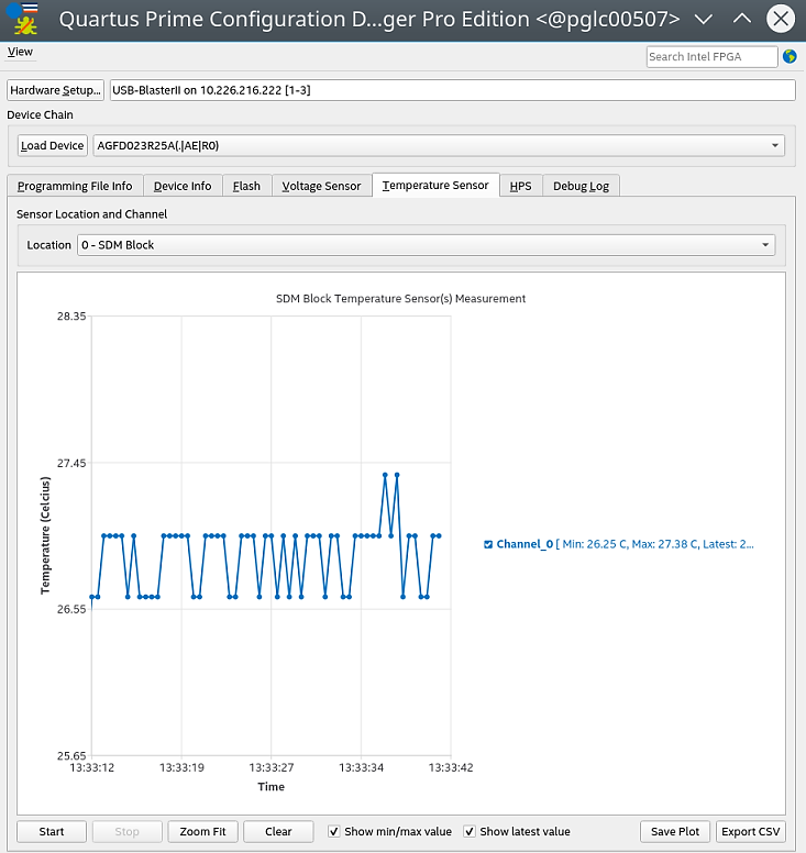
Table 7. Temperature Sensor Channels and Reading for Stratix® 10 DevicesThe supported temperature sensor channel depends on sensor availability on the supported device, availability and type of transceiver tile, and the temperature sensor setup in your design. Channel Corresponding Temperature Reading 0 Core Fabric 1 Bank 1C/1D/1E/1F/8A 2 Bank 1G/1H/1I/1J/8B 3 Bank 1K/1L/1M/1N/8C 4 Bank 4C/4D/4E/4F/9A 5 Bank 4G/4H/4I/4J/9B 6 Bank 4K/4L/4M/4N/9C 7 UIB-Lower 8 UIB-Upper Table 8. Temperature Sensor Channels and Locations for Agilex™ 7 DevicesThe supported temperature sensor channel depends on sensor availability on the supported device, availability and type of transceiver tile, and the temperature sensor setup in your design. Some supported channels are available only to specific tile or selected devices. Refer to the Agilex™ 7 Power Management User Guide for details. Location Supported Channel 0 – SDM Block 1, 0 1 – Core Fabric Lower Left 2, 1, 0 2 – Core Fabric Upper Left 2, 1, 0 3 – Core Fabric Lower Right 2, 1, 0 4 – Core Fabric Upper Right (HPS) 2, 1, 0 5 - Transceiver Lower Left 6, 5, 4, 3, 2, 1, 0 7 - Transceiver Upper Left 6, 5, 4, 3, 2, 1, 0 8 - Transceiver Lower Right 6, 5, 4, 3, 2, 1, 0 10 - Transceiver Upper Right 6, 5, 4, 3, 2, 1, 0