8.2.1. Adding and Parameterizing the RapidIO Component
- In the IP Catalog, find and highlight the RapidIO IP core component and click Add.
- To parameterize your IP core, follow these steps:
- On the Physical Layer page, specify the Device Options settings.
Table 126. Set Physical Layer Device Options Option Value Comment Mode selection 4x Serial Automatically synchronize transmitted ackID Turn off This value is the default value. Send link-request reset-device on fatal errors Turn off This value is the default value. Link request attempts 7 This value is the default value. - Specify the Data Settings values.
Table 127. Set Physical Layer Data Settings Option Value Comment Baud rate 2500 Mbaud This value is the default value. Reference clock frequency 125 MHz This value is the default value. Receiver buffer size 4 Kbytes This value is the default value. Transmit buffer size 8 Kbytes This value is the default value. - Specify the Receive Priority Retry Threshold values.
Table 128. Set Physical Layer Receive Priority Retry Threshold Option Value Comment Receive Priority Retry Threshold Turn on Auto-configured from receiver buffer size This value is the default value. - Click the Transport and Maintenance tab.
- Under Transport Layer, leave all three options turned off.
- Under I/O Maintenance Logical Layer Module, set the parameters.
Table 129. Set Transport Layer Options Option Value Comment Maintenance logical layer interface(s) Avalon® -MM Master and Slave Number of transmit address translation windows 1 This value is the default value. Port write Tx enable Turn off This value is the default value. Port write Rx enable Turn off This value is the default value. - Click the I/O and Doorbell tab.
On the I/O and Doorbell tab, leave all settings at their default values. To fully exercise the design example testbench, you must maintain the default I/O Logical layer Avalon® -MM Master and Avalon® -MM Slave ports. Turning off DOORBELL messaging, the default under Doorbell Slave, reduces resource usage and may be desirable for some applications.
- Click the Capability Registers tab. You can set the Device Register to match your system. Unless your design includes an additional extended feature block, keep the Extended features pointer default value of 0x0100. You can keep the default values for all other parameters.
- Under Data Messages, make sure both options are turned off.
- Click Finish to complete parameterization and add the RapidIO IP core to the Platform Designer (Standard) system.
After you add the RapidIO IP core component to your system, various Avalon® -MM ports are created and shown as connection points in the System Contents tab. Error messages indicate that these ports are not connected.
Figure 42. RapidIO IP Core Added and Avalon® -MM Ports Created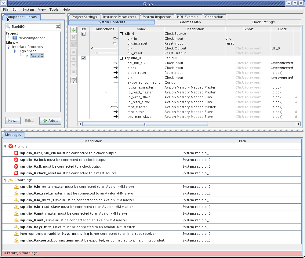
- On the Physical Layer page, specify the Device Options settings.
These errors are resolved as you add the remaining components to your system and make all of the appropriate connections, as described in the following sections.
The default instance name of the RapidIO IP core component is rapidio_0. To run the design example, you must retain the default name. However, in your own system, you can change any default component instance name by right-clicking on the name and then clicking Rename. The component name must be unique; it cannot be the same name as the system name.