Multi Channel DMA Intel® FPGA IP for PCI Express User Guide
A newer version of this document is available. Customers should click here to go to the newest version.
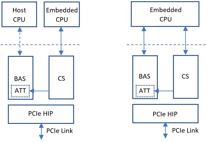
3.6. Root Port Address Translation Table Enablement
The Root Port Address Translation Table (ATT) translates the address driven by the Avalon-MM master connected to the Bursting Avalon-MM Slave (BAS) . For example, if the embedded CPU with the smaller address bus is the master, ATT enables the embedded CPU to access the entire 64-bit PCIe address space. If the host CPU is the master, ATT can be used to translate the host address bus. The following figure shows example use cases.
- ATT Table Address Width (1-9): Sets the depth of ATT. Depth is equal to 2 to the power of number entered.
- ATT Window Address Width (10-63): Sets the number of BAS address bits to be used directly.
When address mapping is disabled, the Avalon-MM slave address is used as-is in the resulting PCIe TLPs. When address mapping is enabled, burst of transactions on the Avalon-MM slave interfaces must not cross address mapping page boundaries. This requirement means (address + 32 * burst count) <= (page base address + page size ). Host software is expected to guarantee this in the Root Port mode and the BAS/CS does not have any mechanism to report the error if this requirement is violated.
When address mapping is enabled, Avalon-MM lower-order address bits are passed through to the PCIe TLPs unchanged and are ignored in the address mapping table.
For example, if you define 16 address mapping windows of 64 KB each at configuration time and program the local CS address 0x3018 and 0x301C with 0x56780000 and 0x00012340 respectively, a read or write transaction to address 0x39AB0 on the bursting Avalon-MM slave interface gets transformed into a memory read or write TLP accessing PCIe address 0x0001234056789AB0.
The number of lower-order address bits that are passed through defines the size of the page and is set by ATT Window Address Width parameter in the IP GUI. If bits [63:32] of the resulting PCIe address are zero, TLPs with 32-bit wide addresses are created as required by the PCI Express standard.
In the figure below, ATT depth is 64. This is set by ATT Table Address Width = 6 (26= 64 deep). Address pass through width is 16. This is set by ATT Window Address Width = 16. This means BAS forwards the lower 16 bit address as is. The upper 6 bits are used to select the ATT entry. In the example, the ATT entry selection is 0x03.
- The host software is expected to program all the ATT registers in the CS for all enabled locations.
- When the AVMM transaction is received on BAS, it detects the address being 32-bit or 64-bit and enables the translation logic in CS as shown above. If the address translation gets enabled, the BAS logic retrieves the translated data from the ATT table as shown in above figure.