6.6.1. AXI Switch Selection in HBM2 IP Catalog GUI
The parameters to enable the AXI switches are editable only when both channels of a channel pair are enabled, as shown in the figure below. When you enable the AXI switch, all four of the corresponding controllers should use the same AXI Data Width and Enable Reorder Buffer options.
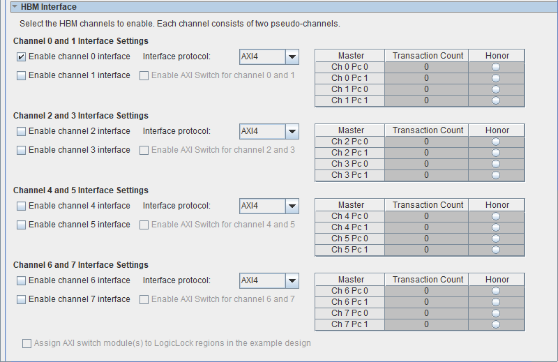
If you enable multiple HBM channels, you can choose to enable the AXI switch for certain channel pairs, and leave the rest as direct AXI connection to AXI master (user logic side). For example, you can enable the AXI switch module for CH0 and CH1, then have direct AXI connection to CH2 and CH3, with that AXI switch disabled.
When you enable the AXI switch, you can edit the master’s arbitration scheme parameter table. By default, the switch uses round-robin arbitration (no honor selected, and transaction count 0).
The soft 4×4 AXI switch provides the following features:
- Provides each AXI master access to memory space of four HBM2 Pseudo Channels (two HBM2 Channels).
- The switch provides access only in the 4×4 configuration. That is, you cannot modify this switch configuration to 2×2 or extended to 8×8, and so forth.
- The switch supports 4×4 access across the AXI Interface signals, including AXI Write address, AXI Write Data, AXI Write response, AXI Read Address and AXI Read data. The switch does not provide the switch capability on the APB side band interface.
- Switch access is as follows:
- Any AXI master can send commands and receive responses from any slave channel.
- Switching from one slave to another slave is treated as a non-posted transaction — that is, the master waits for the slave to provide all the responses back, before switching to the next slave.
- The AXI ID usage when the AXI Switch is enabled is as follows:
- In the AXI switch-enabled mode, the higher-order two bits of the 9-bit AXI ID (awid/arid) are not available and only 7 bits (128 AXI IDs) are available to use as AXI IDs (awid/arid).
- When you do not enable the AXI switch, 9 bits are available to use as AXI IDs.
- The AXI Switch user interface expects that corresponding write data is available prior to accepting the next write command. Hence, you may see discontinuity in write command ready signal (awready) even if the slaves are ready to accept commands. This does not cause any reduction in efficiency. User logic must buffer the write commands if write commands are being sent in a stream.
- AXI Address usage when the AXI Switch is enabled:
- AXI address bus (awaddr/araddr) is 31 bits wide when the 8GB HBM2 is used and 30 bits wide when the 4GB HBM2 is used.
- In comparison, when the AXI switch is not enabled, the AXI addr bus is 29 bits wide when the 8GB HBM2 is used and 28 bits wide when the 4GB HBM2 is used.
- The higher-order 2 bits of the AXI address bus are used to identify the slave for the corresponding AXI request.
When you generate the HBM2 IP with the AXI Switch option enabled, you must drive the following values on the higher-order bits, based on the slave addressed. The same values follow for all the HBM2 channel pairs, for example, HBM2 Channels 2 and 3, 4 and 5 and 6 and 7.
Table 42. AXI Address Higher-Order Bits and Corresponding Slave Addresses AXI Address (Higher-Order 2 bits) Slave Address 00 HBM2 Channel 0/Pseudo Channel 0 01 HBM2 Channel 0/Pseudo Channel 1 10 HBM2 Channel 1/Pseudo Channel 0 11 HBM2 Channel 1/Pseudo Channel 1 Note: The AXI switch does not have the option to restrict access to a specific slave. It is the responsibility of the master to mask access to a specific slave, if needed, and also to ensure the correct slave is accessed by providing the correct Slave AddressThe option to assign an AXI module or modules to Logic Lock regions is available as reference in the HBM2 design example. You can use this in your actual design to improve timing. Final timing closure is based on several factors, including Quartus® Prime timing closure, core logic utilization and core clock frequency.
- AXI address bus (awaddr/araddr) is 31 bits wide when the 8GB HBM2 is used and 30 bits wide when the 4GB HBM2 is used.
- Controller configurations for HBM2 Channels in the switch:
- When you enable the AXI Switch, the controller configurations for the corresponding two HBM2 channels should use the same AXI Data configurations (AXI burst configuration, Data width etc) and Enable Reorder buffer options.
Command Arbitration is needed when multiple masters are competing to access a single slave and require help to efficiently schedule the transactions. The options available help to improve the efficiency of transactions and help to prioritize AXI masters. When AXI masters are not competing for access to a specific slave, all transactions are considered point-to-point and are serviced accordingly. The following arbitration schemes are supported:
- Arbitration scheme 1: Round-Robin
- This is the default arbitration scheme, following the order from AXI master 0 to 3. Transaction Count for Masters is set to 0 and no Honoring is chosen. Every master can issue only 1 transaction, before the next master is granted access. (1 AXI transaction means 1 BL4 or 1 BL8 transaction, based on the burst configuration chosen.)
- Arbitration scheme 2: Honored Master
- This option allows you to select one of the four AXI masters to be Honored and Transaction count set to 0.
- When this option is selected, the master selected is granted the highest priority over the remaining AXI Masters.
- Once this master is serviced, the remaining masters are serviced through round robin arbitration.
- If none of the masters is selected to be honored, all the masters follow Round-Robin priority (Arbitration scheme 1).
- Arbitration scheme 3: Transaction counts
- This arbitration scheme uses transaction counts with or without using the Honored Master option. This scheme sets a transaction-count for each master. The transaction count defines the count of the total transactions the AXI master would like to issue any given time. Each transaction count refers to a single Burst length 4 transaction (32B) or a single pseudo Burst length 8 transaction (64B) at the AXI interface. For example, a transaction count of 10 refers to 10 AXI command transactions that the Master can issue, when granted access. The AXI master can choose to issue all the 10 transactions to 1 AXI slave or divide them as necessary among all AXI slaves or issue fewer than 10 AXI transactions too.
- After a master is granted access to a slave, it can issue all the “Transaction count” number of transactions, provided the master is able to issue them and the corresponding slaves are ready to service the requests. If a slave is not ready to service the master or the master is not ready to issue the expected total transactions, the next master is granted access through the round robin scheme. Every time a master is granted access, the number of allowed transactions resets to the Transaction count value. For example, if the Transaction count for master 0 is set to 50, and master 0 has issued 20 transactions and become idle, master 1 is then granted access. When master 0 is granted access again, master 0 is allowed to perform 50 transactions.
- When you select the honor mode, the transaction count for this master is disabled and the value set to 0, indicating highest priority. This master can issue all its transactions, after which the next master in the round robin scheme is given access.
- Large transaction counts, up to 65535, are supported, however, you must select the appropriate transaction count based on the application needs, as higher transaction count might adversely affect timing closure.
- All configuration for command arbitration occurs at IP generation, not at run time.
- It is advisable to run RTL simulations of representative traffic patterns for your application, to enable the arbitration scheme to be optimized.
Area Overhead Due to Switch
The area utilization due to four instances of the 4×4 AXI switch is ~7.1% (~50k out of total ~700k ALM) for 1 memory stack at four instances of 4×4 AXI switch. The design example provides an example of Logic Lock constraints for better timing closure.
Latency
A maximum of twenty AXI clock cycles of round-trip latency across AXI ports when the transactions are point to point. (This refers to the physical latency from the time the command is received to the time read data is available at the user interface, not including command scheduling or wait times in the command queue.) Additional latency when using the switch is based on the command arbitration logic. The AXI master must wait for all the slave responses to return before switching to another slave.