1. Overview of the Power and Thermal Analyzer
2. Estimating Power Consumption with the Power and Thermal Analyzer
3. Power and Thermal Analyzer (PTA) Graphical User Interface
4. Power and Thermal Analyzer Resource Types
5. Command Line Options and Scripting
6. Factors Affecting the Accuracy of the Power and Thermal Analyzer
7. Document Revision History for the Power and Thermal Analyzer User Guide
A. Measuring Static Power
B. Tcl Command Reference
3.1. PTA - Device Selector Dialog Box
3.2. PTA - Primary GUI Components
3.3. PTA - Hierarchical Design Editor
3.4. PTA - Using Design Hierarchies in the Power and Thermal Analyzer
3.5. PTA - Entering Hierarchy Information Into the PTA
3.6. PTA - Current Drawn per Supply Tab
3.7. PTA - Temperature and Cooling Tab
3.8. PTA - Resource Utilization Panel
3.9. PTA - Register Dynamic Power in Agilex Devices
3.10. PTA - Input Fields
3.11. PTA - Data Entry Error Messages
3.12. PTA - Search Features
3.13. PTA - Filtered Searches
3.14. PTA - Using the Tcl Console to Perform Searches
4.1. PTA - Power Summary
4.2. PTA - Root Entry
4.3. PTA - Instance
4.4. PTA - Logic Resource Type
4.5. PTA - RAM Resource Type
4.6. PTA - DSP Resource Type
4.7. PTA - Clock Resource Type
4.8. PTA - PLL Resource Type
4.9. PTA - I/O Resource Type
4.10. PTA - Transceiver Resource Type
4.11. PTA - Crypto Resource Type
4.12. PTA - NOC Resource Type
4.13. PTA - HBM Resource Type
B.1. add
B.2. copy
B.3. delete
B.4. edit
B.5. export_design_file
B.6. find_instances
B.7. get_available_ips
B.8. get_available_resource_types
B.9. get_available_values
B.10. get_first_error
B.11. get_properties
B.12. get_report
B.13. get_report_names
B.14. get_results
B.15. get_value
B.16. import_design_file
B.17. move
B.18. open_design_file
B.19. pta::get_active_design
B.20. pta::get_defaults
B.21. pta::get_designs
B.22. pta::locate
B.23. pta::set_active_design
B.24. pta::set_family
B.25. recalculate_power
B.26. redo
B.27. save
B.28. set_device
B.29. set_view
B.30. undo
2.4. Estimating Power for Dual-Core Devices
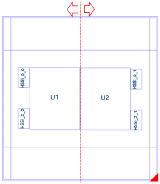
Devices such as the Stratix® 10 1SG10M contain two core dies, and are not directly supported by the PTA.
Power estimation for dual-core devices requires a separate calculator, together with outputs from the 25.1 version of the Power and Thermal Calculator, and some transceiver data.
Package Details
The device package contains two core fabric dies, each with two associated transceivers. In the figure below, U1 and U2 identify the two core fabric tiles, with HSSI_* identifying their respective transceivers.
Figure 4. Dual-core Package Layout
Generating a PTC File and Importing the Data Into the PTA
- In the Quartus® Prime software, generate a PTC file for your design for the U1 tile.
- Create a script file for U1 (for example, design_u1.epe_script) containing the following lines:
import,<U1_name>.ptc
export_output_fields, <U1_name>.epe_dump
- Generate an epe_dump file for U1, by running the following command:
quartus_ptc --epe_test_command=runscript --epe_input=design_u1.epe_script -- family=nadder
Note: You must use the Quartus® Prime software version 25.1 or earlier to run this command. - Download the 1SG10M_Calculator spreadsheet from the Power Estimators and Power Analyzer page.
- Open the 1SG10M_Calculator spreadsheet.
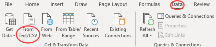
- Import the .epe_dump file into the spreadsheet, by clicking Data in the spreadsheet menu bar, and then selecting the From Text/CSV icon.
Figure 5. Spreadsheet Menu Bar
- Select the <U1_name>.epe_dump file that you generated in step 3, and click Import.
- Ensure that Comma is selected in the Delimiter field, and click Load, as the Specifying Comma Delimiters figure shows.
- After the .epe_dump file loads, copy all the data from the generated worksheet and paste it into the U1 worksheet, replacing any existing data there, as the Newly Generated Worksheet figure shows.
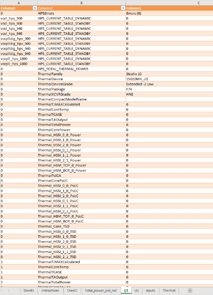
- Repeat the above steps for the U2 die, as the Content Copied Into U1 Worksheet figure shows.
Figure 6. Specifying Comma Delimiters
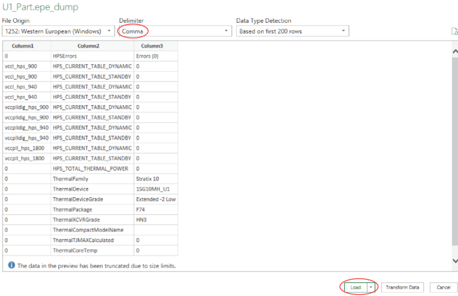
Figure 7. Newly Generated Worksheet
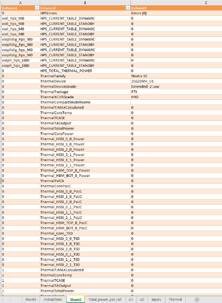
Figure 8. Content Copied into U1 Worksheet
Interpreting the Spreadsheet
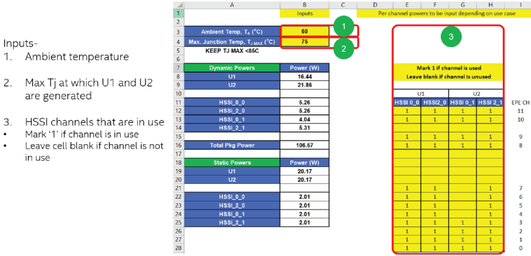
The Total_power_per_rail worksheet shows the power summary for both U1 and U2 — in this case, 1SG10M as a whole device. On the Inputs worksheet, you need to provide the Ambient Temp, Max Junction Temp, TJ-MAX, and HSSI information.
Figure 9. Input Tab
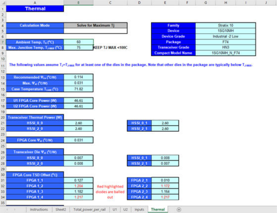
The Thermal worksheet shows the summary for Ψ values and TSD offset values.
Figure 10. Thermal Worksheet