AN 522: Implementing Bus LVDS Interface in Supported Intel® FPGA Device Families
ID
683803
Date
7/31/2018
Public
Overall System Performance
The highest data rate supported by a multipoint BLVDS is determined by looking at the eye diagram of the furthest receiver from a driver. At this location, the transmitted signal has the slowest edge rate and affects the eye opening.
Although the quality of the received signal and the noise margin goal depend on the applications, the wider the eye opening, the better. However, you must also check the receiver nearest to the driver, because the transmission line effects tend to be worse if the receiver is located closer to the driver.
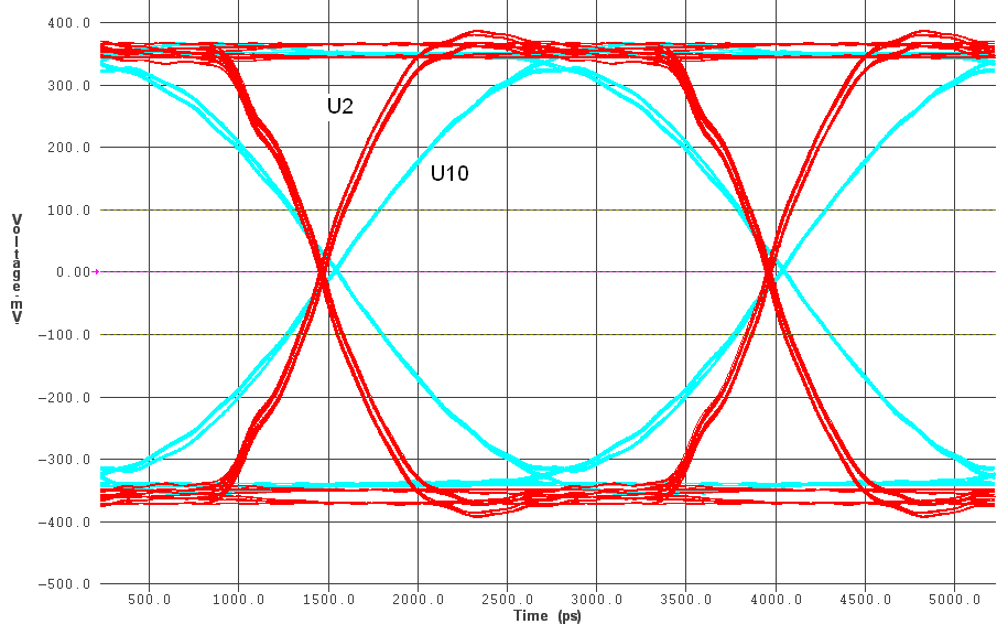
Figure 23. Eye Diagram at 400 Mbps (Driver in U1, Receiver in U2 and U10)This figure illustrates the eye diagrams at U2 (red curve) and U10 (blue curve) for a data rate at 400 Mbps. Random jitter of a 1% unit interval is assumed in the simulation. The driver is at U1 with default current strength and slew rate settings. The bus is fully loaded with optimum RT = 50 Ω. The smallest eye opening is at U10, which is furthest from U1. The eye height sampled at the 0.5 unit interval is 692 mV and 543 mV for U2 and U10, respectively. There is a substantial noise margin with respect to VTH = ±100 mV for both cases.