1.1. Boot Process
1.2. Boot Stages
1.3. Boot Devices
1.4. Second-Stage Boot Loader Support Package Generator Tool
1.5. Generating a Boot Loader with an External Flash Boot Device
1.6. Boot and FPGA Configuration
1.7. Boot Debugging
1.8. Appendix A: Building the UEFI Boot Loader
1.9. Revision History for Arria 10 SoC Boot User Guide
1.5.4. Boot Loader Generation Example Using a NAND Flash Controller
- Launch the SoC EDS embedded command shell:
$ ~/intelFPGA/16.1/embedded/embedded_command_shell.sh - Launch the BSP Editor tool from the SoC EDS embedded command shell:
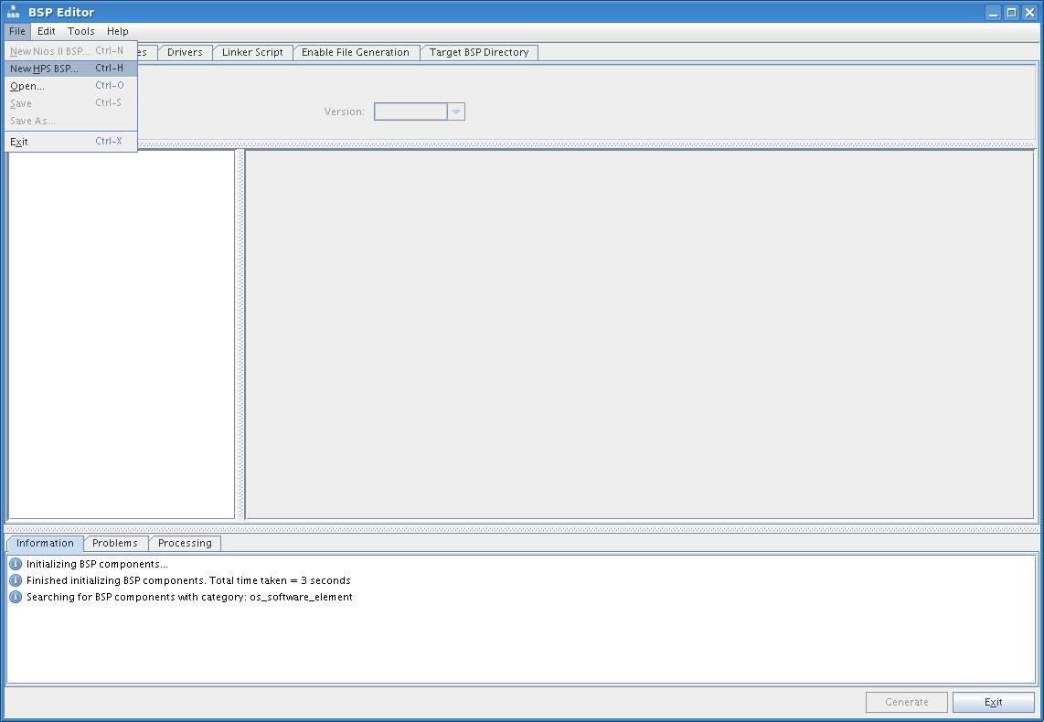
$ bsp-editor - Create a new HPS BSP in the window by selecting File > New HPS BPS.
Figure 29. Selecting New BSP Editor Window
- In the New BSP pop-up window, configure the following:
- Specify a hardware HPS hand-off folder in the Preloader settings directory.
- Specify the boot loader sources folder in the BSP target directory text box.
- Specify the boot loader configuration and settings file location in the BSP Settings File name text box.
Figure 30. Configuring New BSP Settings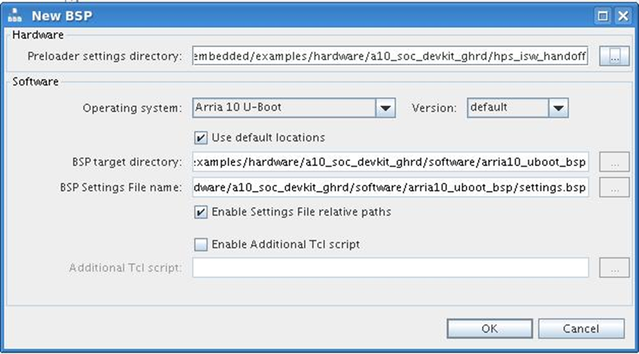
- Click OK to close the New BSP pop-up window.
- In the BSP Editor window, specify the source boot_device (NAND) in the main menu tab.
Figure 31. Selecting Boot from NAND Device in BSP Editor Window
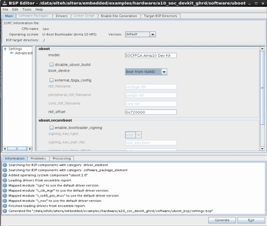
- Select Generate and the boot loader and U-Boot source files are created in the folder you specified as the BSP target directory.
- Change to the U-Boot boot loader source directory and build the image:
$ cd ~/a10_soc_devkit_ghrd/software/arria10_uboot_bsp
$ make
The following items are generated in the ~/a10_soc_devkit_ghrd/software/arria10_uboot_bsp/ folder:
Table 7. Boot Loader Executable Images File Description u-boot_w_dtb.bin U-boot executable with device tree binary uboot_w_dtb-mkpimage.bin U-boot executable with device tree binary wrapped in mkpimage header Note: If you choose to use UEFI as a second-stage boot loader source, refer to the "Appendix A: Building the UEFI Boot Loader" section at this point. - Prepare the boot loader image, U-Boot device tree and FPGA design on the boot device. For more information, please refer to the RocketBoards.org website.