Stratix V Avalon-MM Interface for PCIe Solutions: User Guide
8.1. Connecting the Transceiver Reconfiguration Controller IP Core
The Transceiver Reconfiguration Controller IP Core is available for V-series devices and can be found in the Interface Protocols/Transceiver PHY category in the IP Catalog. When you instantiate the Transceiver Reconfiguration Controller the Enable offset cancellation block and Enable PLL calibration options are enabled by default. For Gen3 variants, you should also turn on Enable adaptive equalization (AEQ) block.
A software driver for the Transceiver Reconfiguration Controller IP Core, Altera PCIe Reconfig Driver IP core, is also available in the IP Catalog under Interface Protocols/PCIe. The PCIe Reconfig Driver is implemented in clear text that you can modify if your design requires different reconfiguration functions.
As this figure illustrates, the reconfig_to_xcvr[ <n> 70-1:0] and reconfig_from_xcvr[ <n> 46-1:0] buses connect the two components. You must provide a 100–125 MHz free‑running clock to the mgmt_clk_clk clock input of the Transceiver Reconfiguration Controller IP Core.
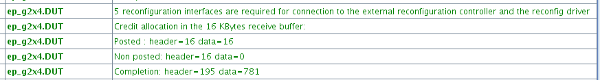
Initially, each lane and TX PLL require a separate reconfiguration interface. The parameter editor reports this number in the message pane. You must take note of this number so that you can enter it as a parameter value in the Transceiver Reconfiguration Controller parameter editor. The following figure illustrates the messages reported for a Gen2 ×4 variant. The variant requires five interfaces: one for each lane and one for the TX PLL.
When you instantiate the Transceiver Reconfiguration Controller, you must specify the required Number of reconfiguration interfaces as the following figure illustrates.
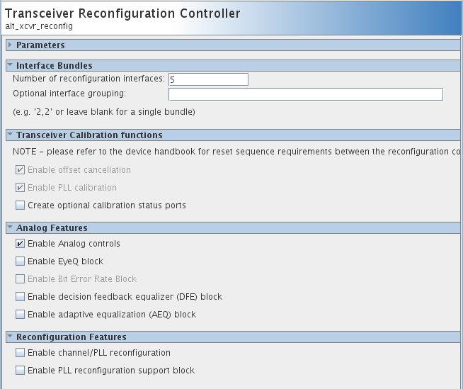
The Transceiver Reconfiguration Controller includes an Optional interface grouping parameter. Transceiver banks include six channels. For a ×4 variant, no special interface grouping is required because all 4 lanes and the TX PLL fit in one bank.