Double Data Rate I/O (ALTDDIO_IN, ALTDDIO_OUT, and ALTDDIO_BIDIR) IP Cores User Guide
ID
683148
Date
6/19/2017
Public
1.1. ALTDDIO Features
1.2. ALTDDIO Common Applications
1.3. ALTDDIO Resource Utilization and Performance
1.4. ALTDDIO Parameter Settings
1.5. ALTDDIO Functional Description
1.6. Design Example: 8-Bit DDR Divider Using ALTDDIO_BIDIR
1.7. ALTDDIO_IN IP Core Signals
1.8. ALTDDIO_OUT IP Core Signals
1.9. ALTDDIO_BIDIR IP Core Signals
1.10. Verilog HDL Prototype
1.11. VHDL Component Declaration
1.12. VHDL LIBRARY-USE Declaration
1.13. Double Data Rate I/O (ALTDDIO_IN, ALTDDIO_OUT, and ALTDDIO_BIDIR) IP Cores User Guide Archives
1.14. Document Revision History
1.6.4. Functional Results—Simulate the Divider Design in the ModelSim* - Intel® FPGA Edition Software
Simulate the design in the ModelSim* - Intel® FPGA Edition software to generate a waveform display of the device behavior.
To set up the ModelSim* - Intel® FPGA Edition software, follow these steps:
- Unzip the ALTDDIO_ex2_msim.zip file to any working directory on your PC.
- Browse to the folder in which you unzipped the files and open the ALTDDIO_ex2.do file in a text editor.
- In line 1 of the ALTDDIO_ex2.do file, replace <insert_directory_path_here> with the directory path of the appropriate library files. For example, C:/altera/71/modelsim_ae/altera/verilog/stratix
- On the File menu, click Save.
- Start ModelSim* - Intel® FPGA Edition .
- On the File menu, click Change Directory.
- Select the folder in which you unzipped the files. Click OK.
- On the Tools menu, click Execute Macro.
- Select the ALTDDIO_ex2.do file and click Open. This is a script file for ModelSim that automates all the necessary settings for the simulation.
- Verify the results by looking at the Waveform Viewer window.
You can rearrange signals, remove redundant signals, and change the radix by modifying the script in the ALTDDIO_ex2.do file.
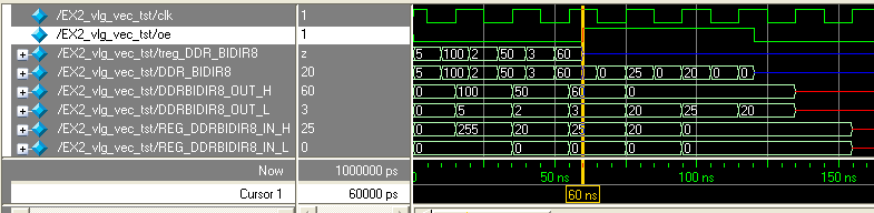
Figure 8. ModelSim Simulation ResultsThis figure shows the expected simulation results in ModelSim* - Intel® FPGA Edition software.
Related Information