Intel® Acceleration Stack User Guide: Intel FPGA Programmable Acceleration Card N3000
2.1. Cooling Requirements
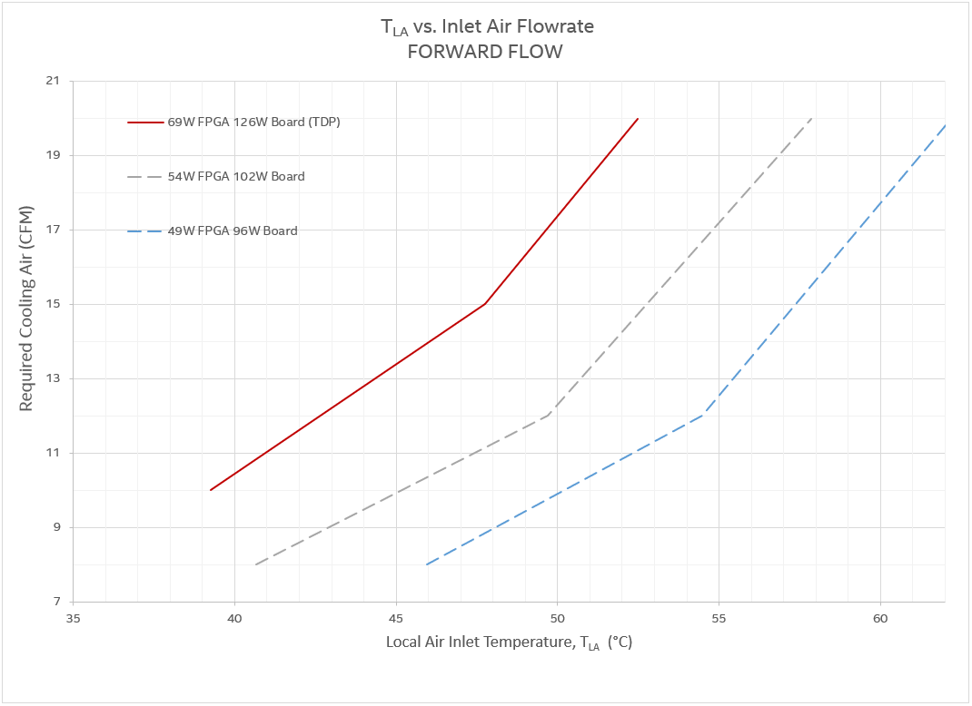
The high performance devices installed on the Intel® FPGA PAC N3000 require server based forced air cooling to maintain proper operating temperature. This section provides air flow requirements for the Intel® FPGA PAC N3000. Sufficient airflow keeps the Intel® Arria® 10 GT junction temperature below 95 °C. Each data point corresponds to minimum airflow (Y-axis) through the card for a corresponding card inlet temperature (X-axis).
- Required Cooling Airflow (CFM): Volumetric flow rate, in cubic feet per minute, of air passing through the PCIe faceplate of the Intel® FPGA PAC N3000.
- TJ FPGA Junction Temperature
- TLA Local Ambient Temperature2: Temperature of forced air as it enters the Intel® FPGA PAC N3000.
Note: In many systems, TLA is higher than the room ambient due to heating affects of chassis components.
| Parameters | Maximum Values |
|---|---|
| Intel® Arria® 10 FPGA Thermal Design Power (TDP)3 | ≤ 69 W |
| Intel® FPGA PAC N3000 Thermal Design Power (TDP) | ≤ 126 W |
| Recommended FPGA Maximum Operating Temperature | 95°C |
| FPGA TJ-MAX or Thermal Protection Shutdown | 100°C |
| Maximum TLA (forward airflow) | 51°C |
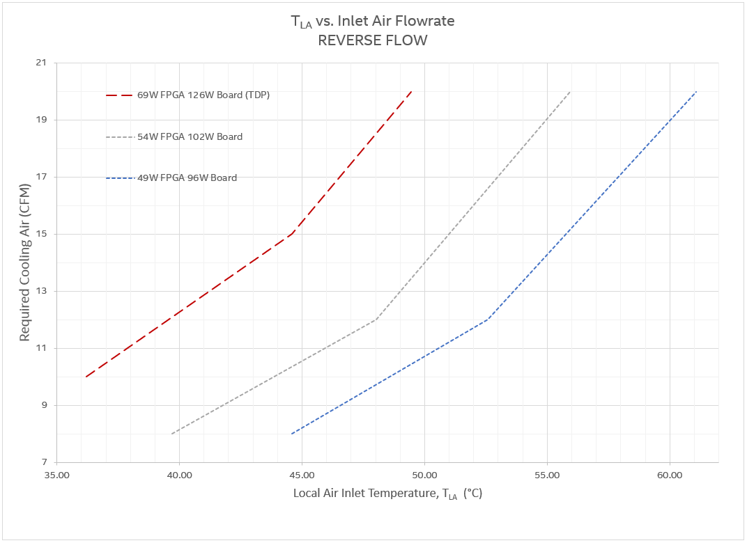
| Maximum TLA (reverse airflow) | 45°C |
| To maintain TJ = 95°C | |||||
|---|---|---|---|---|---|
| FPGA Power < 49 W Board Power < 96 W |
FPGA Power < 54 W Board Power < 102 W |
FPGA Power < 69 W Board Power < 126 W (TDP) |
|||
| Max. TLA (°C) | Air Flow (CFM) | Max. TLA (°C) | Air Flow (CFM) | Max. TLA (°C) | Air Flow (CFM) |
| 46 | 8 | 40.7 | 8 | 39.2 | 10 |
| 54.5 | 12 | 49.8 | 12 | 47.8 | 15 |
| 62 | 20 | 57.9 | 20 | 52.3 | 20 |
| To maintain TJ = 95°C | |||||
|---|---|---|---|---|---|
| FPGA Power < 49 W Board Power < 96 W |
FPGA Power < 54 W Board Power < 102 W |
FPGA Power < 69 W Board Power < 126 W (TDP) |
|||
| Max. TLA (°C) | Air Flow (CFM) | Max. TLA (°C) | Air Flow (CFM) | Max. TLA (°C) | Air Flow (CFM) |
| 44.6 | 8 | 39.8 | 8 | 36.1 | 10 |
| 52.6 | 12 | 48 | 12 | 44.7 | 15 |
| 61 | 20 | 56 | 20 | 49.4 | 20 |
Intel® Arria® 10 FPGA TDP cannot be obtained from on-board BMC sensors. Use the Intel® Quartus® Prime Power Analyzer to verify compliance with this value for your design.