Intel® Acceleration Stack User Guide: Intel FPGA Programmable Acceleration Card N3000
ID
683040
Date
6/14/2021
Public
1. About this Document
2. System Requirements
3. Hardware Installation
4. Installing the OPAE Software
5. OPAE Tools
6. Sample Test: Native Loopback
7. Installing the Intel XL710 Driver
8. Configuring Ethernet Interfaces
9. Testing Network Loopback Using Data Plane Development Kit (DPDK)
10. Graceful Shutdown
11. Single Event Upset (SEU)
12. Document Revision History for Intel Acceleration Stack User Guide: Intel® FPGA PAC N3000
A. Troubleshooting
B. Upgrade your Intel® FPGA PAC N3000 with Production Version of BMC and Intel® Arria® 10 Image
C. Configure the 4.19 Kernel
D. fpgabist Sample Output
3.1. Installing the Intel® FPGA PAC N3000
Complete these steps to install the Intel® FPGA PAC N3000:
- Power down the system.
- Plug the Intel® FPGA PAC N3000 into a PCIe x16 physical and x16 electrical slot on the motherboard.
- Connect the auxiliary power to the 12 V 6-pin connector using an applicable cable.
Note: Make sure the auxiliary power cable does not block airflow to the Intel® FPGA PAC N3000.
- Enable the following options in the BIOS:
- Intel VT-x (Intel Virtualization Technology for IA-32 and Intel 64 Processors)
- Intel VT-d (Intel Virtualization Technology for Directed I/O)
- For network testing, you can insert a loopback module into each QSFP28 port.
Note: ESD protection is required while handling the Intel® FPGA PAC N3000.Warning: Take caution when you are inserting and removing the cards into PCIe slots. The bottom side of the card has capacitors and resistors that can be knocked off if the cards scrapes against edges or corners of the slot in the chassis.Figure 6. Example of QSFP Non-optical ModulesThis is a 25 GbE QSFP setup.
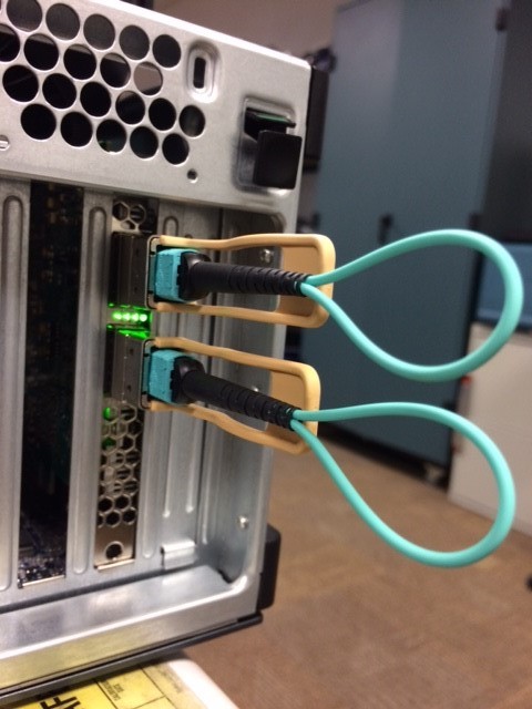
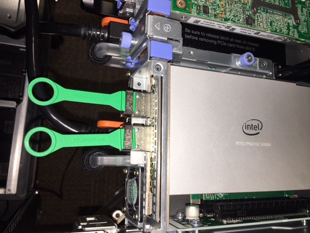 Figure 7. Example of QSFP Loopback Optical Modules
This figure shows the correct orientation of the QSFP module for optical loopback testing. The loopback configuration consists of two Intel 40GBASE-SR4 QSFP+ optical modules and two 10Gtek 12-Core MPO OM3 Fiber Optic Loopback Cables.
- Power on the system and observe the Ethernet status LEDs which are located between the QSFP connectors. The LED operation is described in the table below:
Table 4. LED Behavior LED Type Description Connectivity LED Yellow means link is up with link speed of 10G. Green means link is up with link speed of 25G. Off means link is down. Activity LED Green blinking at 1 Hz means link activity present. Off means link is down or no activity. All LEDs blinking yellow It means either: - 12 V Auxiliary or PCIe edge supply voltage is below 10.46 V or
- FPGA core temperature reaches 100°C or
- Board temperature reaches 85°C
You should check the following:- Card insertion in PCIe slot.
- 12 V Auxiliary connection on the Intel® FPGA PAC N3000 and on the server motherboard.
- Fan setting for cooling air flow. Sufficient airflow is required whenever the Intel® FPGA PAC N3000 is powered on.
For details on the location of Connectivity and Activity LEDs, refer to the Intel FPGA Programmable Acceleration Card N3000 Data Sheet.
Figure 8. Ethernet Status LEDs Power-On IndicationThis figure is an example of 25G configuration where both Ethernet links are UP with ongoing Ethernet activity.
Note: If your server is set up with secure boot, the OPAE Remote Setup (RSU) command will not function. This RSU limitation is due to secure boot having the following limitations:
- Using kexec to start an unsigned kernel image.
- Hibernation and resume from hibernation.
- User-space access to physical memory and I/O ports.
- Module parameters that allow setting memory and I/O port addresses.
- Writing to MSRs through /dev/cpu/*/msr.
- Use of custom ACPI methods and tables.
- ACPI APEI error injection.