GTS AXI Multichannel DMA IP for PCI Express* User Guide
ID
847470
Date
8/25/2025
Public
1. Overview
2. Quick Start Guide
3. Configuring and Generating the GTS AXI Multichannel DMA IP for PCI Express
4. Integrating the IP With Your Application
5. Simulating the IP
6. Validating the IP
7. Known Issues
A. Functional Description
B. Software Programming Model
C. Registers
D. Document Revision History for the GTS AXI Multichannel DMA IP for PCI Express*
2.1.1. Downloading and Installing Quartus® Prime Software
2.1.2. Configuring and Generating the GTS AXI Multichannel DMA IP for PCI Express
2.1.3. Configuring and Generating the GTS AXI Streaming IP for PCI Express
2.1.4. Configuring and Generating the GTS System PLL Clocks IP
2.1.5. Configuring and Generating the GTS Reset Sequencer IP
2.1.6. Configuring and Generating the Reset Release IP
2.1.7. Instantiating and Connecting the IP Interfaces
2.1.8. Simulate, Compile and Validate the Design on Hardware
4.4.1. PCIe AXI-Stream TX Interface (ss_tx_st)
4.4.2. PCIe AXI-Stream RX Interface (ss_rx_st)
4.4.3. Control and Status Register Interface (ss_csr_lite)
4.4.4. Transmit Flow Control Credit Interface (ss_txcrdt)
4.4.5. Configuration Intercept Interface (CII)
4.4.6. Completion Timeout Interface (ss_cplto)
4.4.7. Function Level Reset (FLR) Interface
4.4.8. Control Shadow Interface (ss_ctrlshadow)
4.4.9. Error Interface
4.5.1. H2D AXI-Stream Manager (h2d_st_initatr)
4.5.2. D2H AXI-Stream Subordinate (d2h_st_respndr)
4.5.3. H2D/D2H AXI-MM Manager (dma_mm_initatr)
4.5.4. BAM AXI-MM Manager (bam_mm_initatr)
4.5.5. BAS AXI-MM Subordinate (bas_mm_respndr)
4.5.6. PIO AXI-Lite Manager (pio_lite_initiatr)
4.5.7. HIP Reconfiguration AXI-Lite Subordinate (user_csr_lite)
4.5.8. User Event MSI-X (user_msix)
4.5.9. User Event MSI (user_msi)
4.5.10. User Function Level Reset (user_flr)
4.5.11. User Configuration Intercept Interface
4.5.12. Configuration Slave (cs_lite_respndr)
A.1.1.1. H2D Data Mover
A.1.1.2. D2H Data Mover
A.1.1.3. Descriptors
A.1.1.4. AXI4-Lite PIO Manager
A.1.1.5. AXI-MM Write (H2D) and Read (D2H) Manager
A.1.1.6. AXI-Stream Manager (H2D) and Subordinate (D2H)
A.1.1.7. User MSI-X
A.1.1.8. User Function Level Reset (FLR)
A.1.1.9. Control and Status Registers
B.1.6.1. ifc_api_start
B.1.6.2. ifc_mcdma_port_by_name
B.1.6.3. ifc_qdma_device_get
B.1.6.4. ifc_num_channels_get
B.1.6.5. ifc_qdma_channel_get
B.1.6.6. ifc_qdma_acquire_channels
B.1.6.7. ifc_qdma_release_all_channels
B.1.6.8. ifc_qdma_device_put
B.1.6.9. ifc_qdma_channel_put
B.1.6.10. ifc_qdma_completion_poll
B.1.6.11. ifc_qdma_request_start
B.1.6.12. ifc_qdma_request_prepare
B.1.6.13. ifc_qdma_descq_queue_batch_load
B.1.6.14. ifc_qdma_request_submit
B.1.6.15. ifc_qdma_pio_read32
B.1.6.16. ifc_qdma_pio_write32
B.1.6.17. ifc_qdma_pio_read64
B.1.6.18. ifc_qdma_pio_write64
B.1.6.19. ifc_qdma_pio_read128
B.1.6.20. ifc_qdma_pio_write128
B.1.6.21. ifc_qdma_pio_read256
B.1.6.22. ifc_qdma_pio_write256
B.1.6.23. ifc_request_malloc
B.1.6.24. ifc_request_free
B.1.6.25. ifc_app_stop
B.1.6.26. ifc_qdma_poll_init
B.1.6.27. ifc_qdma_poll_add
B.1.6.28. ifc_qdma_poll_wait
B.1.6.29. ifc_mcdma_port_by_name
2.1.4. Configuring and Generating the GTS System PLL Clocks IP
Following is the procedure to generate the GTS System PLL Clocks IP.
- Select GTS System PLL Clocks IP in the IP Catalog.
- Select GTS System PLL Clocks IP (Library → Interface Protocols → Transceiver PHY → GTS System PLL Clocks IP) and then click Add.
- Specify a top-level name for your new custom IP variation and the directory for it. The IP Parameter Editor saves the IP variation settings in a file named <your_ip>.ip.
- Click Create. The IP Parameter Editor appears as shown in the figure below.
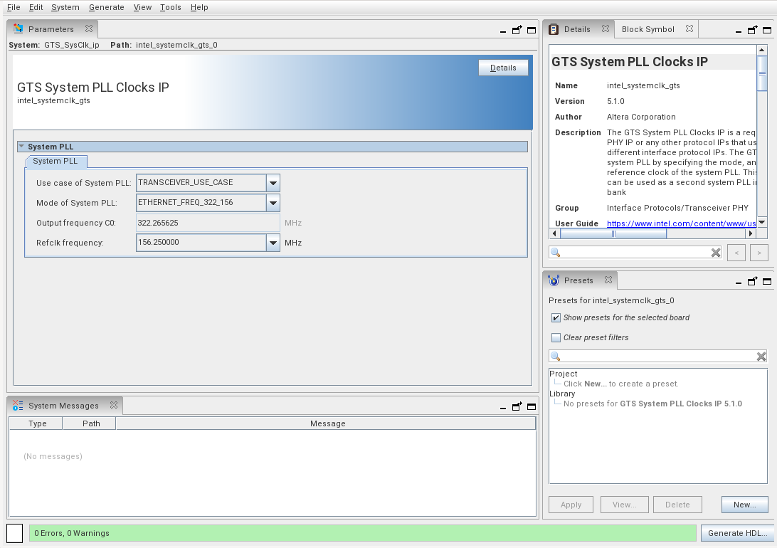
- Set the parameters while referring to the following table:
Parameter Setting Use case of System PLL TRANSCEIVER_USER_CASE Mode of System PLL Select the setting that matches the PLD clock frequency in the GTS AXI Streaming IP. - PCIe 4.0 x8: PCIE_FREQ_500/PCIE_FREQ_450/PCIE_FREQ_400/PCIE_FREQ_350/PCIE_FREQ_300/PCIE_FREQ_250/User_PCIE-based_Configuration_200.
- PCIe 4.0 x4: PCIE_FREQ_350/PCIE_FREQ_300/PCIE_FREQ_250/User_PCIE-based_Configuration_200.
- PCIe 3.0 x8: PCIE_FREQ_350/PCIE_FREQ_300/PCIE_FREQ_250/User_PCIE-based_Configuration_200.
- PCIe 4.0 x2/x1, PCIe 3.0 x4/x2/x1: PCIE_FREQ_300/PCIE_FREQ_250/User_PCIE-based_Configuration_200.
Output frequency C0 Automatically set based on the Mode of System PLL setting. Refclk frequency 100 MHz - Generate the GTS System PLL Clocks IP.
- Click Generate HDL. The Generation dialogue box appears. Specify the output file generation options.
- Click Generate. The IP variation files are generated according to your specifications.
- Click Close when the IP generation is complete. The IP Parameter Editor adds the top-level.ip file to the current project automatically. If you are prompted to manually add the .ip file to the project, click Project → Add/Remove Files in Project to add the file.