AN 999: Drive-on-Chip with Functional Safety Design Example: Agilex™ 7 Devices
ID
823627
Date
7/04/2024
Public
1. About the Drive-on-Chip with Functional Safety Design Example for Agilex™ 7 Devices
2. Getting Started
3. Rebuilding the Drive-on-Chip Design
4. Functional Description of the Drive-On-Chip with Functional Safety Design Example for Agilex 7 Devices
5. HPS Channel Safety Software
6. Drive-on-Chip Design Recommendations and Disclaimers
7. Document Revision History for AN 999: Drive-on-Chip with Functional Safety Design Example for Agilex 7 Devices
2.1. Software Requirements for the Drive-On-Chip with Functional Safety Design Example for Agilex 7 Devices
2.2. Hardware Requirements for the Safe Drive-On-Chip with Functional Safety Design Example for Agilex 7 Devices
2.3. Downloading and Installing the Design
2.4. Installing Python
2.5. Creating an SD Card Image
2.6. Setting Up your Development Board for the Drive-On-Chip with Functional Safety Design Example for Agilex 7 Devices
2.7. Debugging and Monitoring the Drive-On-Chip with Functional Safety Design Example for Agilex 7 Devices with Python GUI
2.8. Looking into the Drive-On-Chip Output
3.1. Generating the Platform Designer System
3.2. Generating and Building the NiosV/g BSP for the Drive-On-Chip Design Example
3.3. Compiling the Hardware in the Intel Quartus Prime Software
3.4. Modifying the Motor Control Software Application
3.5. Generating .jic and .rbf files After Hardware Modifications
3.6. Recreate an SD Card Image
3.7. Modifying the HPS Safety Function Application
4. Functional Description of the Drive-On-Chip with Functional Safety Design Example for Agilex 7 Devices
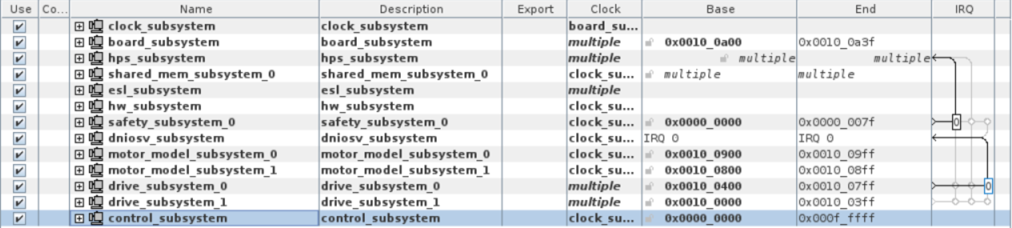
The Platform Designer high-level system includes many subsystems. These subsystems allow the system to work appropriately.
- The clock_subsystem and board_subsystem contain blocks related to the board resources such buttons, switches, LEDs, reference clocks, resets. They provide the clocks and resets for the other subsystems.
- The hps_subsystem is an instance of the Agilex 7 HPS that runs the HPS safe channel application in Linux. EMIF to on-board DDR4 chip includes presets and connections of the HPS2FPGA bridges to other subsystems. The subsystem includes an instance of DDR4 EMIF to interface with on-board memory chip with all presets and connections to the HPS2FPGA bridges to other subsystems.
- The shared_mem_susbsystem enables cross comparison data to pass between the FPGA and HPS as part of the safety concept. A memory location where the FPGA channel and the HPS channel read and write the necessary safety payloads.
- The esl_subsystem is an internal (FPGA fabric) implementation of the external safety logic. In a production functional safety application, you remove this block and you implement it in a separate device from the Agilex device.
- The hardware_subsystem collects information off the device that you can use to implement safety features such as voltage and temperature monitoring and validation.
- The safety_subsystem implements one channel of the the safety concept in the FPGA. This safety channel is currently attached to the speed monitoring of Axis0
- The subsystems dniosv_subsystem, motor_model_subsystem_8, drive_subsystem_ and control_subsystem are blocks related to motor control and motor modeling. For more information on these blocks, refer to AN 994: Drive-On-Chip Design Example for Agilex 7 Devices.
Figure 12. Platform Designer Top-Level Design