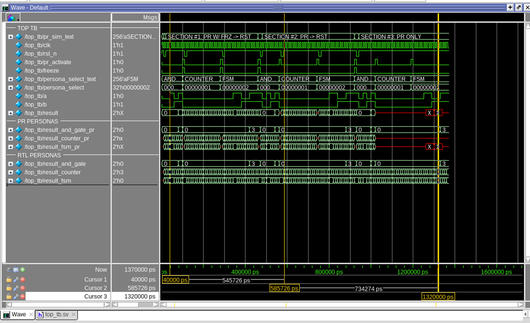
10. PR Simulation Results
By looking at the Simulation waveforms, you can verify whether the signals behave consistently with your expectations. The simulation in this tutorial works as follows:
- The simulation logic in the testbench top_tb drives the pr_activate, persona_select and freeze signals.
- The testbench triggers a PR transition by asserting the pr_activate signal.
- The persona_select signal selects the current persona. In addition, it also controls the PR input and output multiplexer select input lines to control the correct input and output of the persona.
- The pr_activate signal forces the output of the PR output multiplexer to unknown (X) values (for freeze logic verification). In addition, it also triggers the PR simulation register model to show unknown (X) value in all registers of the persona (for reset sequence verification).
- The freeze signal freezes the PR region output and sets to known value while the PR transition is occurring.
- After some time transpires, the testbench de-asserts pr_activate signals and resets the PR persona.
The simulation of top_sim module is separated into the following sections:
- Initialization
- Initial Reset
- Section #1: PR with Freeze, then reset (PR W/ FRZ → RST)
- Section Reset
- Section #2: PR, then Reset (PR → RST)
- Section Reset
- Section #3: PR Only (PR ONLY)
Figure 12. Simulation Waveform