A newer version of this document is available. Customers should click here to go to the newest version.
1.3. Simulating the Design
Figure 5. Simulating the Design flow
To run example design simulation, follow these steps:
- Generate the necessary simulation setup files.
- Using GUI method:
- Open the Intel® Quartus® Prime Project in Intel® Quartus® Prime directory.
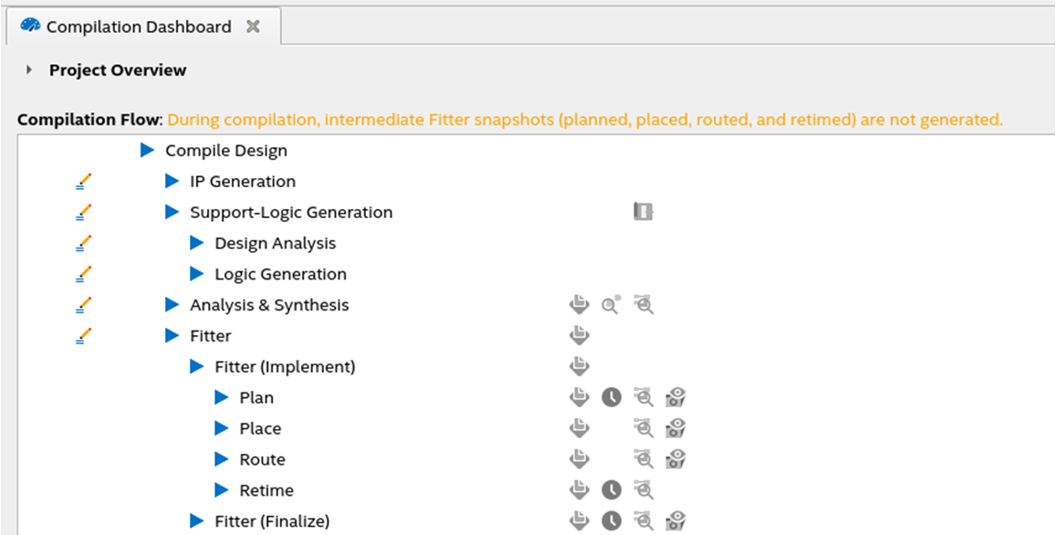
- Run Support-Logic Generation to generate the transceiver RTL files.
Figure 6. Support-Logic Generation in Compilation Dashboard
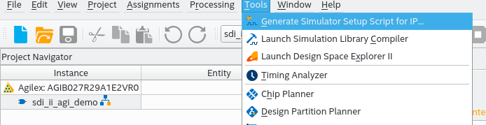
- To generate the simulation setup files, click Tools > Generate Simulator Setup Script for IP....
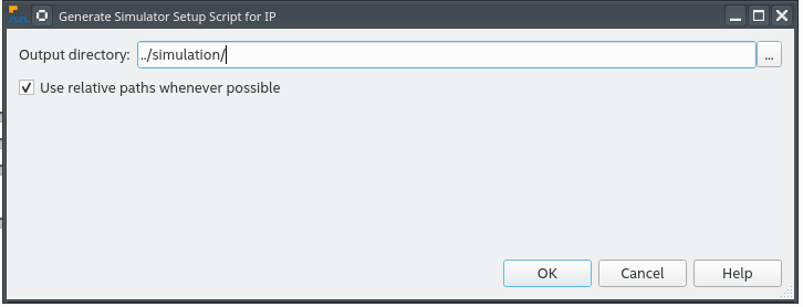
- Set the output directory to .../simulation.
Figure 7. Generating Simulation Setup File Using GUI
- Using command-line:
- Open a command-line terminal.
- Make sure your environment variable (QUARTUS_ROOTDIR) points to the bin/bin64 in your Intel® Quartus® Prime installation directory
- Change the current directory to the generated simulation folder in your terminal.
- Run this command source sim_setup_gen.sh.
- Using GUI method:
- Go to simulation folder.
- Go to the desired simulator folder and run the simulation script:
- ModelSim* SE or Questa* FE: Bring up the simulator GUI, change directory to mentor folder and type do mentor.do
- VCS* : Go to synopsys/vcs folder and type source vcs_sim.sh.
- VCS* MX : Go to synopsys/vcsmx folder and type source vcsmx_sim.sh
- Xcelium* : Go to xcelium folder and type source xcelium_sim.sh
- A successful simulation ends with the following message:
