2.1.11. System Options
Use the System Option windows to set the simulation setting.
System tab
Figure 90. Advanced Link Analyzer System Options Window: System Tab
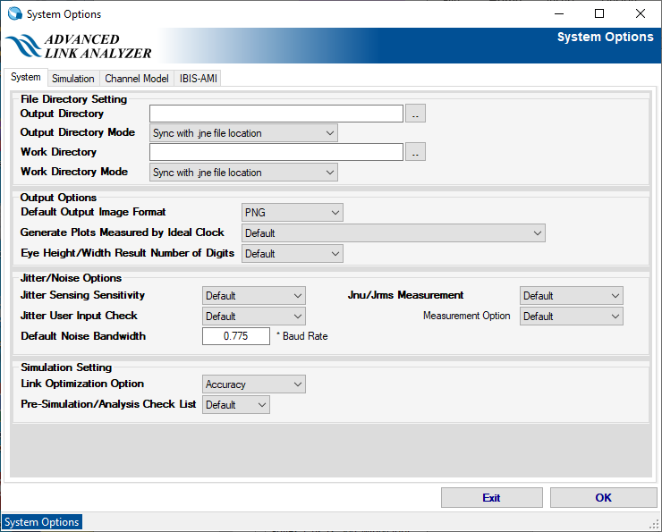
- Output Directory—Specify an output directory for the simulation results according to the Output Directory Mode setting.
- Output Directory Mode
- Sync with .jne file location—Automatically sets the output directory to the directory location when you create .jne/.jneschm with the Save or Save as command.
- As specified in the Output Directory—Sets the output directory to the location specified in the Output Directory text box.
- Work Directory—Specify a work directory for the simulator according to the Work Directory Mode setting. By default, sets the work directory location as the output directory.
- Work Directory Mode
- Sync with .jne file location—Automatically sets the work directory to the directory location when you create .jne/.jneschm with the Save or Save as command.
- As specified in the Work Directory—Sets the work directory to the location specified in the Work Directory text box.
Note: Advanced Link Analyzer can generate temporary data files during simulations. You can reduce the access time by using local storage space for storing temporary files. If you have a remote default data storage such as a network attached storage, set the working directory to local storage space to reduce simulation time. - Default Output Image Format—Set the default output image format to PNG, JPG, or GIF.
- Generate Plots Measured with Ideal Clock
- Yes—Always generate plots that are measured with the ideal clock.
- Do not plot when RX CDR is enabled—Skip ideal clock-based plots in RX outputs. (default value)
- Do not plot when TX scope is enabled—Skip ideal clock-based plots in TX outputs.
- Do not plot when the TX scope, RX CDR, or both are enabled—Skip ideal clock-based plots when the TX scope, RX CDR, or both are enabled.
- Jitter Sensing Sensitivity—Select the sensitivity of jitter detection when Advanced Link Analyzer performs jitter analysis (Beta feature in the current version). The selections are: Default, Ideal, Low, Medium, and High. The Default setting is equivalent to the Ideal setting.
- Jitter User Input Check—If enabled, Advanced Link Analyzer checks if the specified jitter is valid. The checker can usually be used to catch mistakes such as incorrect jitter amplitude unit. The default is Enable.
- Default Noise Bandwidth—Advanced Link Analyzer uses this parameter to automatically scale the bandwidth of noise sources, when the bandwidth setting is Auto, according to the simulation baud rate. The default value is 0.775 of link baud rate. The default noise bandwidth factor can be modified by editing JNEye_Config.dat via the NoiseBWScalar parameter. For instance, if you want to change the noise bandwidth scaler to 2.5 times the link baud rate, the following two line text can be specified:
%% NoiseBWScalar 2.50 - Jnu/Jrms Measurement—Enable or Disable PAM4 Jnu/Jrms measurement within a simulation. The default is Disable.
- Jnu/Jrms Measurement Option—Specify PAM4 Jnu/Jrms measurement option. The default is IEEE 802.3 120D.
- Link Optimization Option— The choices are Accuracy or Speed. The default is Accuracy. By selecting Speed, the link optimization process runs faster at the cost of possibly less optimal solutions.
Simulation tab
Figure 91. System Options Window: Simulation Tab
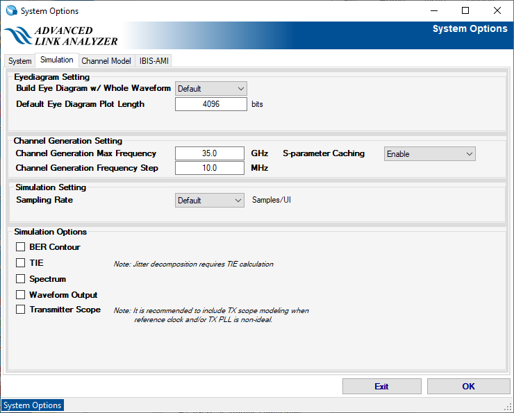
- Default Eye Diagram Plot Length—This parameter controls the waveform length used to construct the eye diagram when the Build Eye Diagram w/ Whole Waveform option is disabled. You can increase the length as long as the length is less than the simulation length. The default value is 4096 bits.
- Build Eye Diagram w/ Whole Waveform—If Enable is selected, Advanced Link Analyzer uses the whole simulated waveform to build the eye diagrams. If the simulation length is large, this takes more time. The default setting is Enable.
- Channel Generation Max Frequency—Sets the default maximum frequency of the channel models generated in Advanced Link Analyzer. The default value is 35 GHz.
- Channel Generation Frequency Step—Sets the default frequency step of the channel models generated in Advanced Link Analyzer. The default value is 10 MHz.
- S-parameter Caching—If Enable is selected, the last read S-parameter file is cached in memory for faster access and processing. Doing this greatly improves GUI performance when reading a multiple-lane S-parameter file with large file size. You can disable this feature.
- Sampling Rate—Specify simulation sampling rate. The default selection is 32.
- Simulation Options—You can selectively enable or disable certain analysis features in a simulation:
- BER Contour
- Tie Interval Error (TIE): If TIE analysis is disabled, jitter decomposition is also disabled.
- Spectrum
- Waveform Output
- Transmitter Scope
Channel Model tab
Figure 92. System Options Window: Channel Model Tab
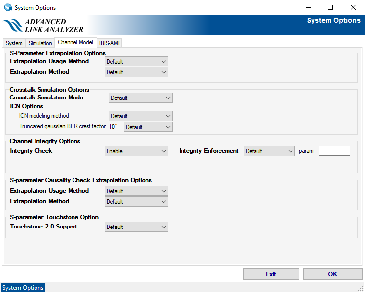
- S-Parameter Extrapolation Options
- Extrapolation Usage Method—This menu selects the method used in the extrapolation S-parameter channel model.
- Default—The S-parameter is extrapolated but capped with the amplitude value at the end (the highest frequency) of the S-parameter data.
- Always Apply—The S-parameter is extrapolated without restriction.
- Extrapolation Method—This menu selects the extrapolation method.
- Default—Linear extrapolation.
- IL Fitting Extrapolation—Extrapolation is done by insertion loss fitting.
- Extrapolation Usage Method—This menu selects the method used in the extrapolation S-parameter channel model.
- Crosstalk Simulation Options
- Crosstalk Simulation Mode
- Default—Crosstalk is simulated using waveforms.
- ICN—Crosstalk is simulated using the Integrated Crosstalk Noise (ICN) method.
- ICN modeling method—ICN can be simulated using Truncated Gaussian or Gaussian method. The default is Truncated Gaussian.
- Truncated Gaussian BER crest factor—The crest factor of the truncated Gaussian distribution, calculated based on the bit error rate (BER) target value. The default BER target value is 10-6.
Numerous studies show that the ICN method more accurately reflects crosstalk's impact in high-speed serial links. For example, use the ICN method if the crosstalk sources are uncorrelated to the victim channel. If the crosstalk is correlated to the victim channel, use the waveform-based crosstalk method instead.
When simulating crosstalk using the ICN method, Intel recommends using the Truncated Gaussian method because noises are usually bounded in real systems.
- Crosstalk Simulation Mode
- Channel Integrity Options—Enable or disable channel integrity checking in Advanced Link Analyzer. The default setting is Enable. Choose Disable if Advanced Link Analyzer has issues opening or accessing certain S-parameter models.
- Integrity Enforcement— Select how the integrity enforcement is applied in the simulation. An integrity enforcement example is causality.
- Type 1: Enforce integrity on individual channel components
- Type 2: Enforce integrity on overall channel after cascading
- Type 3: Enforce integrity both on individual channel component and after channel cascading
- Disable: Disable integrity enforcement. Default setting is Disable.
- S-parameter Causality Check Extrapolation Options
- Extrapolation Usage Method—Same as the same name entry in the S-Parameter Extrapolation Options. This entry only applies during S-parameter causality checking.
- Extrapolation Method—This menu selects the extrapolation method during S-parameter causality checking.
- Default—Insertion loss fitting based extrapolation method.
- Last Amplitude Value—Linear extrapolation is used, but the amplitude is capped by the last amplitude value.
- S-parameter Touchstone Option—Touchstone 2.0 Support.
- Enable—Enable Touchstone 2.0 support. (default value)
- Disable—Disable Touchstone 2.0 support.
IBIS-AMI tab
Figure 93. System Options Window: IBIS-AMI Tab
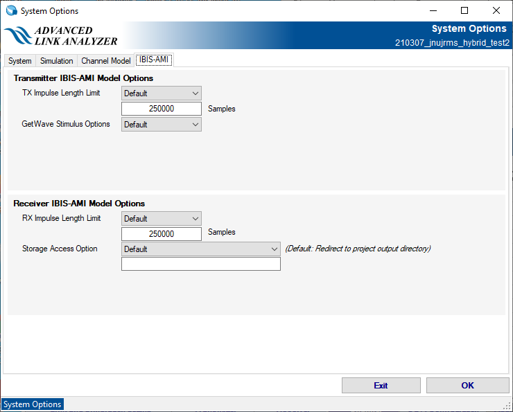
- TX Impulse Length Limit—Selects options for controlling the length of the impulse response sent into the transmitter IBIS-AMI model. Choose Auto to let Advanced Link Analyzer determine the length. Choose Custom to set the impulse response length in the text box below the pull-down menu. The default value for custom impulse response length is 250000 samples. The default setting is Custom.
- GetWave Stimulus Options—Selects the IBIS-AMI GetWave input stimulus type. Choose Logic for the simulator to feed the GetWave input with a pre-determined logic amplitude level between +1 and -1. Choose Analog so that the input waveform can have a varying amplitude. The default setting is Logic.
- RX Impulse Length Limit—Selects options for controlling the length of the impulse response sent into the receiver IBIS-AMI model. Choose Auto to let Advanced Link Analyzer determine the length. Choose Custom to set the impulse response length in the text box below the pull-down menu. The default value for custom impulse response length is 250000 samples. The default setting is Custom.
- Storage Access Option—Selects options for how the RX IBIS-AMI model handles its output location. Choose Redirect to project output directory so that the RX IBIS-AMI output data is written to the project’s output folder. Choose No change so that there is no output redirection. Choose Custom location to specify a folder location of your choice through the directory browser. The default setting is Redirect to project output directory.