2.1.1. Constructing Communication Links in the Link Designer Module
The Link Designer module allows you to construct communication links.
| Transmitter (TX) Component |
Channel/Link Component |
Receiver (RX) Component |
|---|---|---|
| Intel® Agilex™
Stratix®
Arria®
Generic
IBIS-AMI
Intel® Cyclone® 10
|
Channel
Crosstalk
Channel Designer
Basic Component
Clock Path Component
Link Component
|
Intel® Agilex™
Stratix®
Arria®
Generic
IBIS-AMI
Intel® Cyclone® 10
|
Advanced Link Analyzer supports the following simulations:
- Intel TX to Intel RX
- Intel TX to non-Intel RX
- Non-Intel TX to Intel RX
- Non-Intel to non-Intel link simulations are not supported.
- For Intel® devices that are not listed in Table 3, contact My Intel® support, and acquire the IBIS-AMI models.
- Devices supported with wrapper technology can be added, removed or updated to Advanced Link Analyzer after the tool is installed. Please refer to IBIS-AMI Wrapper for further details.
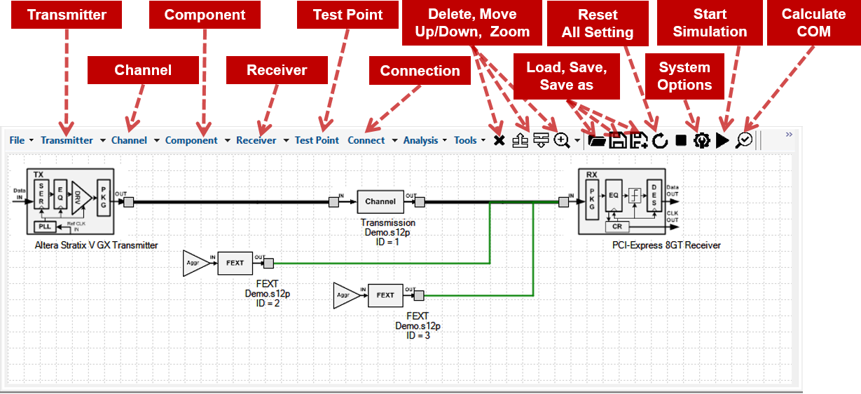
A link consists of a transmitter, a receiver, and one or more channel/link components. Select the transmitter, receiver, and channel/link components from the menus at the top of the Link Designer workspace.
After the link components are placed into the workspace, click Connect to connect the components. In connect mode, one or two connectors are shown on each component. Connect the link components by dragging the line from one connector to another. Two types of connections are provided in Link Designer: Right Angled Line and Straight Line. Right Angled Line is the default connection method. Test points can be manually placed into the link by clicking Test Point and connecting to the desired location in the link.
The following rules of link construction apply to the Link Designer module:
- A transmitter can only have one output port or connector.
- A receiver can only have one input port or connector.
- A channel/link component has one input and one output port.
- A test point can only be connected to an input port.
- A connection between two components can be established from an output port to an input port.
- A transmitter cannot be connected directly to a receiver.
- A clock path channel component can only connect to another clock path component and be terminated by a clock path transmitter or receiver.
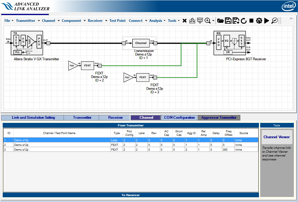
A link establishment checking algorithm runs constantly in the background, checking whether a link is established for simulations. When a link is established between a transmitter and receiver, the link lines become bold and color-coded. Bold black lines indicate signal paths, green lines indicate crosstalk signal paths, brown lines indicate clock signal paths, and purple lines point to test point port locations. The following figure shows an example link topology. A table of link components is displayed in the Channel tab for reference.
When a channel component (for example, a transmission line, connector, far-end crosstalk (FEXT), near-end crosstalk (NEXT), package, AC coupling capacitor, or shunt capacitor) is chosen, the Channel Wizard helps you verify or set the channel configuration.
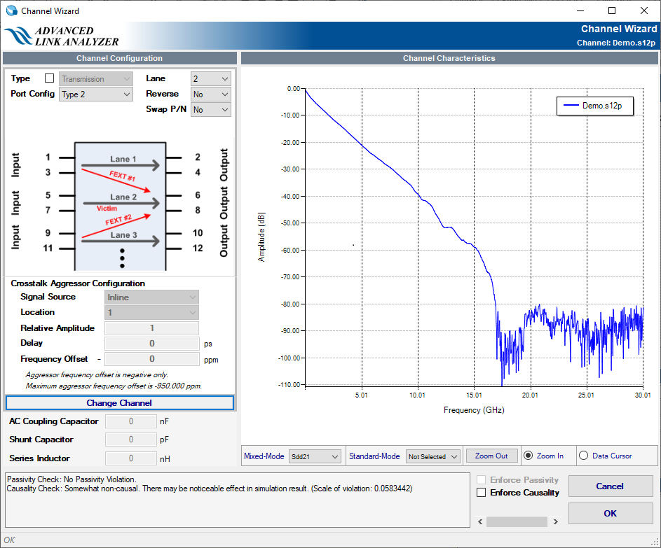
The Channel Wizard displays the channel characteristics and allows you to verify the correctness of the channel component, such as a component represented by an S-parameter. The Channel Wizard allows you to select the following components:
- channel type
- port configuration
- signal lanes (for multiple-lane S-parameters with eight and more ports)
- crosstalk aggressor location (for multiple-lane S-parameters)
- aggressor
- series inductance value (in nH)
- AC coupling capacitor value (in nF)
- shunt capacitance value (in pF)
The Channel Wizard checks the integrity of the channel component in terms of passivity and causality characteristics. When the Channel Wizard detects passivity and causality violations, it displays messages about the severity of the violations in the text box on the left of the OK button. The levels of channel integrity violation are listed in the following tables. Advanced Link Analyzer provides the option to enforce or improve causality of the selected channel during a simulation when Enforce Causality is turned on.
| Passivity Violation Check Results | Impact on Link Simulation Accuracy | Recommendations |
|---|---|---|
| No Passivity Violation | No impact | No action needed |
| Slight Passivity Violation | There may not be a noticeable effect in the simulation result. | The channel model can be further improved but the improvement in terms of simulation results accuracy can be small. |
| Minor Passivity Violation | There may be a noticeable effect in the simulation result. | The channel model can be further improved. Simulation result accuracy can be reduced. |
| Passivity Violation | Simulation result impact | The channel model needs to be regenerated (by design tools) or re-taken (by instruments). The confidence of simulation results using this channel model is low. |
| Causality Violation Check Results | Impact on Link Simulation Accuracy | Recommendations |
|---|---|---|
| Channel is causal | No impact | No action needed |
| Slight non-causal | There may not be a noticeable effect in the simulation result | The channel model can be further improved but the improvement in terms of simulation results accuracy can be small. |
| Somewhat non-causal | There may be a noticeable effect in the simulation result | The channel model can be further improved. Simulation result accuracy can be reduced. |
| Non-causal | Simulation result impact | The channel model needs to be regenerated (by design tools) or re-taken (by instruments). The confidence of simulation results using this channel model is low. |
An existing channel can be changed by adding a new channel component or by modifying an existing channel component. Right-click in the Link designer module and select Properties.
When using the package channel component, follow these guidelines:
- Package models should be placed next to the devices.
- Each device can have only one package model. Therefore, the external package model can only be used when the device’s package type is “Custom”.
- The package model type is used by the simulation engine to identify the boundary of the devices and generate a waveform for observation and analysis.
- The package model is treated the same way as the “Transmission” channel type. Therefore, use the “Transmission” channel type even if the model represents a physical package (in your system) but it is not a package of the TX and RX.