A newer version of this document is available. Customers should click here to go to the newest version.
2.1.3.2. Transmitter Options
Termination tab
This section specifies the transmitter impedance.
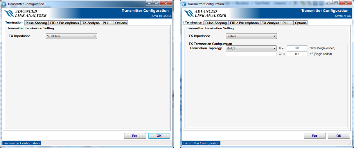
For selected Intel devices, use the TX Impedance pull-down menu to select a termination configuration. You can also customize the termination configuration by selecting the Custom option. When the Custom TX Impedance method is chosen, the termination can be configured as follows:
- Ideal TX termination—The transmitter is ideal with a 50 ohms (single-ended) termination.
- Non-ideal TX termination—Select one of the following options:
- R—Transmitter impedance is modeled as a resistance R ohms (single-ended).
- R//C1—Transmitter impedance is modeled as an RC network with a parallel resistor (in ohms) and a capacitance (in pF).
- File Input (Frequency Real Imaginary)—Transmitter impedance is modeled by a frequency-dependent complex impedance table described in the input file.
For an Intel transmitter, the default termination configurations are automatically selected and specified.
Pulse Shaping tab
Advanced Link Analyzer supports three pulse shaping methods for Custom transmitters:
- Edge Rate—A pulse-shaping filter is generated by using a Gaussian low-pass filter that matches the specified edge rate.
- Rise/Fall Time —A pulse shaping filter is generated by using a Gaussian low-pass filter that matches the specified 20%-80% rise/fall time.
- S-parameter—A pulse-shaping filter is specified by your S-parameter file. Only the differential insertion loss (for example, Sdd21), is applied in the pulse shaping.
- For standards-based transmitters, for example, PCI Express* 8GT/16GT, pulse shaping types and configurations are set by the transmitter model and, hence, cannot be changed. You can override the default standards-based transmitter model setting by turning on Override generic/standard device setting.
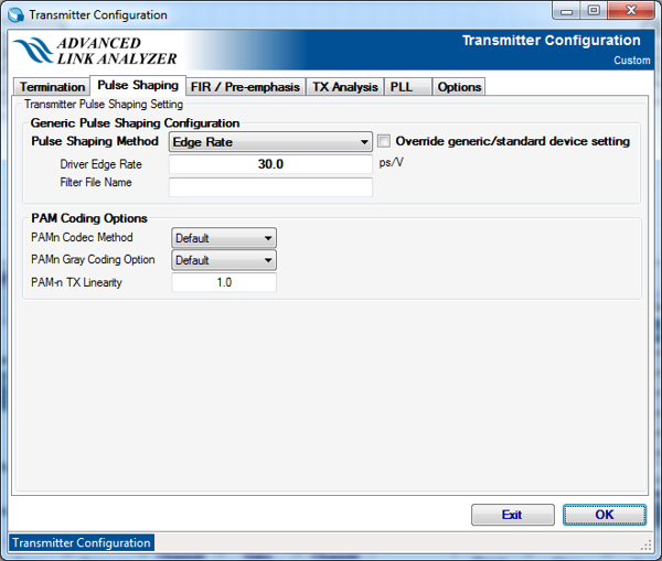
PAM-n Options
- PAM-n Codec Method— Select PAM-n coder/decoder method. The selections are Default, Gray, and Linear. The default setting is Gray coding.
- PAM-n Gray Coding Option— Select Gray coding options. Selections are Default, MSB first, and LSB first. The default setting is MSB first.
- PAM-n TX Linearity— Set the linearity of PAM-n output waveform. PAM-n linearity means mismatch between amplitude levels. The default value is 1.0. The PAM-n TX linearity is defined in the same way as specified in IEEE 802.3 PAM-4 transmitter linearity (RLM).
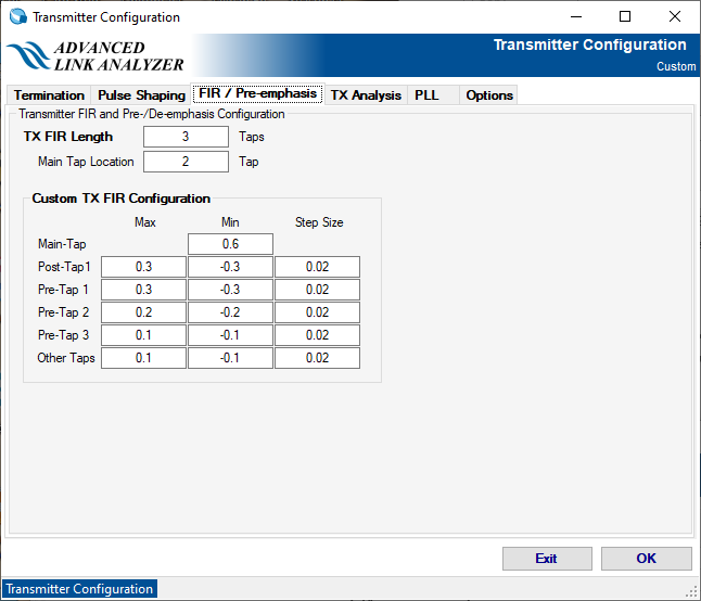
FIR / Pre-emphasis tab
Specify the length of the TX FIR and the location of the main cursor tap. This setting is only valid for the Custom transmitter type.
When Custom TX is selected, TX FIR configuration table is displayed. You can configure the range of TX FIR coefficients to be used in the TX EQ optimization process.
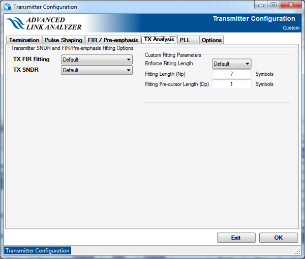
TX Analysis
- TX FIR Fitting— TX FIR Fitting measures the effective transmitter equalization approximated by FIR (finite impulse response) coefficients. The selections are Default, IEEE 802.3bj/CEI-25G-LR, CEI-56G-MR, Custom, and Disable. The default setting is Disable.
- TX SNDR— TX SNDR measures the signal-to-distortion-and-noise ratio of transmitter output. The selections are Default, IEEE 802.3bj/CEI-25G-LR, CEI-56G-MR, Custom, and Disable. The default setting is Disable.
- Enforce Fitting Length— This setting is in effect when custom TX FIR Fitting is selected. The selections are Default, Enable, and Disable. When Enable is selected, the fitting algorithm ignores the transmitter configuration and performs the FIR fitting per the tap-length specified in the Fitting Length and Fitting Pre-cursor Length settings. When Disable is selected, the FIR fitting uses the transmitter's FIR configuration to perform the fitting calculation. The default setting is Enable.
- Fitting Length— TX FIR fitting length.
- Fitting Pre-cursor Length— TX FIR fitting pre-cursor tap length.
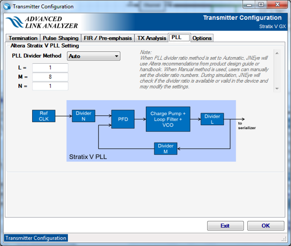
PLL tab
Use this panel to set the custom PLL divider ratio. This panel provides an alternative to Advanced Link Analyzer’s automatic divider ratio configuration. For example, Intel transmitters provide three programmable dividers: L, M, and N. You can set the divider ratio manually. Refer to Intel transceiver documentation for PLL setting recommendations.
Options tab and Die Model tab
Reserved. These tabs are blank.