A newer version of this document is available. Customers should click here to go to the newest version.
2.1.9. Repeater and Retimer Configurations
Advanced Link Analyzer supports repeater and retimer simulations. A repeater is a device that can be placed within a link where it can provide additional equalization capabilities. It is typically constructed with two major stages: an equalizer stage and a driver stage. The equalizer stage usually contains continuous-time linear equalizer (CTLE) circuitry that compensates the channel before and, possibly, after the repeater depending on the design of the driver stage. The driver stage usually amplifies the equalized signal and may contain an emphasis function so that it may compensate the channel after the repeater. Depending on the driver stage design, a repeater can be a linear repeater, where the driver maintains linear characteristics within the majority of the signal amplitude range, or a non-linear repeater, where a limiting amplifier between the equalizer stage and driver stage can sharpen the waveform’s transition time. Both linear and non-linear repeater simulations are supported in Advanced Link Analyzer.
Similar to a repeater, a retimer is a device that can be placed within a link where it provides additional equalization and jitter/noise cleaning capabilities. A retimer is constructed with two major stages: an equalizer stage, which is equipped with the clock data recovery (CDR) circuitry, and a driver stage. The equalizer with a CDR stage first compensates the channel effects for the link before the retimer, and then the CDR recovers the bit time and data for its output. During this process, it not only compensates for channel effects, but also resets or reduces jitter and noises that may come from the reference clock, transmitter, or other channel components. Also, with the presence of a CDR, more advanced equalization schemes, such as decision feedback equalizer (DFE), can be incorporated in a retimer. The driver stage is similar to that of a repeater. A retimer is non-linear by nature as both the bit time and amplitude are re-generated.
- Simulation mode: Hybrid mode or Full Waveform mode. Repeater/Retimer simulations in Statistical simulation mode are not supported.
- Repeater and retimer model format: The repeater and retimer models must be in IBIS-AMI format. IBIS version 6.0 (and later) officially supports repeater and retimer simulations and models are available from vendors. The only exception is that, for certain linear repeaters, vendors may provide their models in S-parameter format. If this is the case, users can just treat the repeater S-parameter as a regular channel component and place/connect it in the schematic editor.
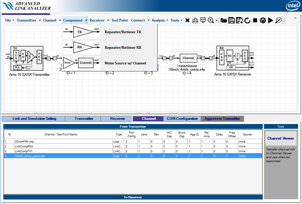
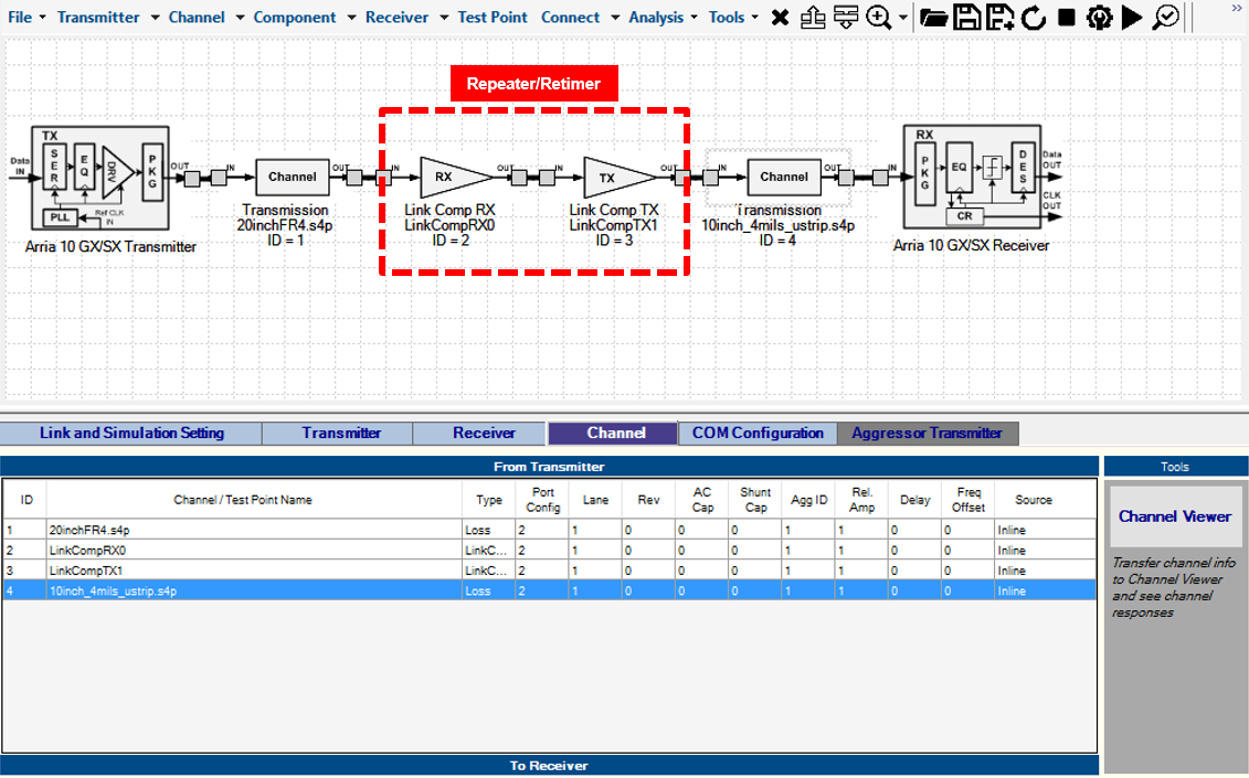
A repeater/retimer IBIS-AMI model consists of two internal models: an IBIS-AMI receiver model, i.e., the equalizer/CDR stage, and an IBIS-AMI transmitter model, i.e., the driver stage. In Advanced Link Analyzer, you explicitly place a pair of a receiver link component (Repeater/Retimer RX) plus a transmitter link component (Repeater/Retimer TX) in the schematic editor for a repeater/retimer model. Figure 78 shows the repeater/retimer GUI entries and Figure 79 shows a typical repeater/retimer link configuration. Note that while Advanced Link Analyzer does enforce or limit how the link components are connected within a link, you have to ensure the repeater/retimer RX and repeater/retimer TX model are connected in the correct signal flow order and no other link or channel component is placed between the repeater/retimer RX and TX models.
Note that the repeater and retimer IBIS-AMI model may be provided in various formats. The equalizer/CDR stage model, which is with IBIS receiver component type, and the driver stage, which is with IBIS transmitter component type, may belong to the same IBIS model or may be provided in two separate IBIS models. Please consult the vendors for the usage.