A newer version of this document is available. Customers should click here to go to the newest version.
2.1.10. Noise Source Link Component
Advanced Link Analyzer supports noise source generation and simulation in the link level. While most high-speed serial links’ noise are generated by the transmitter and receivers (and their supporting networks and components like power supplies, reference clock, and crosstalk), many industrial standards use external noise sources, which are applied on pre-defined test points within a link, for channel or device compliance tests. Notable industrial standards such as PCISIG and IEEE 802.3 use such external noise injection schemes. With the support of noise source generation and simulation capabilities, we can accurately model such compliance test conditions in Advanced Link Analyzer.
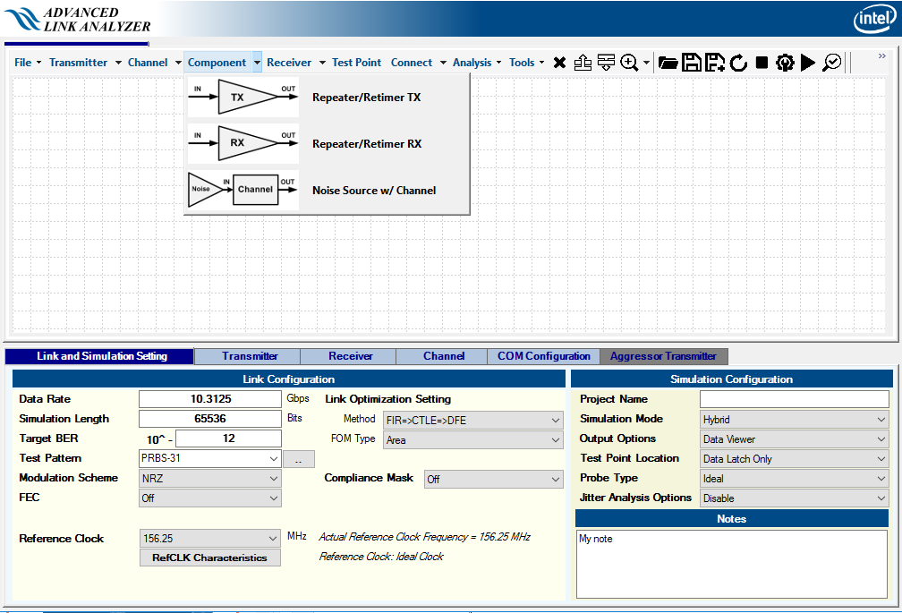
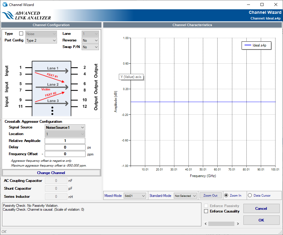
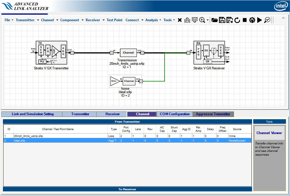
Figure 86 shows the GUI entry for noise source generator. Turning Noise Source w/ Channel on makes the Advanced Link Analyzer Channel Wizard appear (see Figure 87). By default, an ideal channel (no loss with ideal impedance) is chosen. If there is a channel between the noise generator and the test point, you can click the Change Channel button and select a different channel file. Note that the Signal Source pull-down menu is set to NoiseSouce1 by default. You can also configure or modify the noise source’s relative amplitude, delay, or frequency offset in the same way as setting a crosstalk aggressor. After click OK button, the noise source can be placed in the schematic design space. A typical link topology with a noise source is shown in Figure 88.
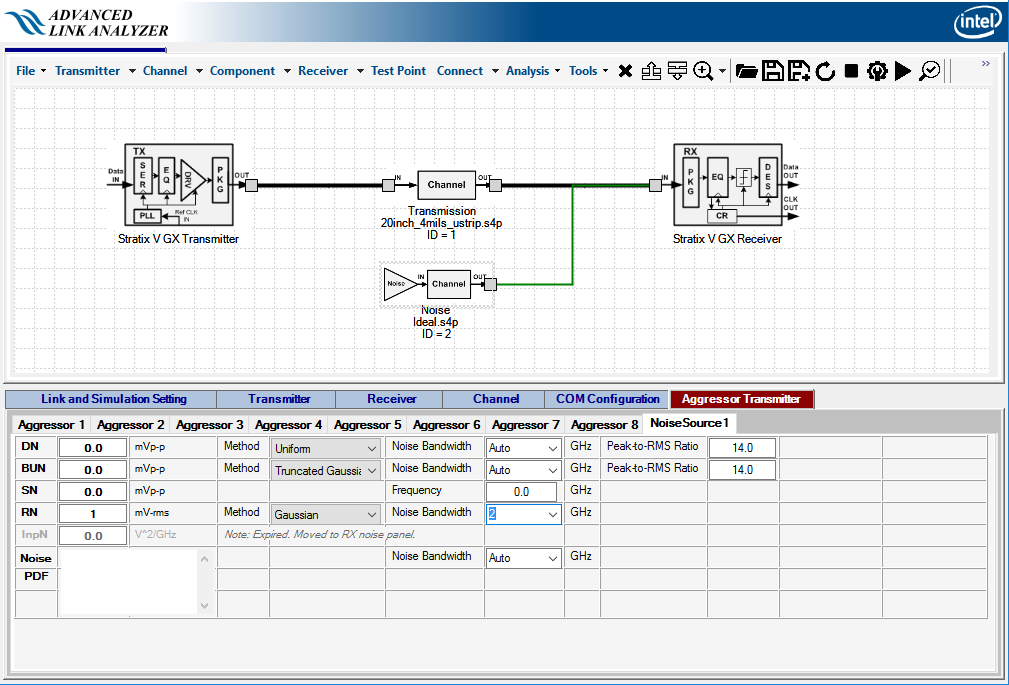
- DN: Deterministic noise in mV. DN can be generated using a uniform distribution, dual-Dirac, or truncated Gaussian method. The default DN method is uniform.
- BUN: Bound uncorrelated noise in mV. The noise characteristics selection is same as DN. The default method is Truncated Gaussian method with a Peak-to-RMS ratio of 14.
- SN: Sinusoidal noise with peak-peak amplitude in mV with specified frequency in GHz.
- RN: Random noise in mV-rms. You can further limit the RN bandwidth to the frequency you specify in GHz.
- Noise PDF: Not supported.