2.3.3.2. P/N De-skew Strategy on Differential Pairs
High-speed data on differential links must be de-skewed to achieve the maximum eye opening and avoid mode conversion. There are various ways to de-skew a differential pair: in the via anti-pad area or in the trace.
There are some signal integrity issues with de-skewing in traces:
- Impedance fluctuation (discontinuity) issue: For tightly coupled differential traces, the de-skew trombone on one of the P/N legs creates loosely coupled sections that cause a high impedance unless the impedance of those sections is tuned in layout.
- Mode conversion issue: The de-skew trombone on one of the P/N legs may have less delay per unit length compared to the straight trace on the other leg. For more details, refer to http://www.sigcon.com/Pubs/edn/serpentine.htm
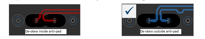
There are also some signal integrity issues with de-skewing inside the via anti-pad area:
- The trace delay is smaller in the via anti-pad area due to less coupling to the reference planes.
- The trace impedance discontinuity due to the length mismatch inside the via anti-pad can also cause signal integrity issues.
Figure 16. De-skew Inside/Outside the Via Anti-pad
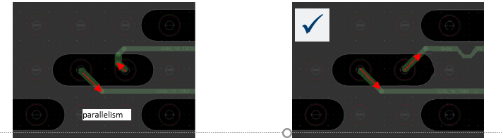
- For de-skewing with single-ended breakout routing, the trace parallelism inside the anti-pad with no ground reference causes NEXT effect (see the following figure). However, the NEXT effect is not significant with 1 mm pin-pitch vias and short coupled lengths as shown in the left image of the picture.
Figure 17. Parallelism, Crosstalk and De-skew in the Via Anti-pad Region
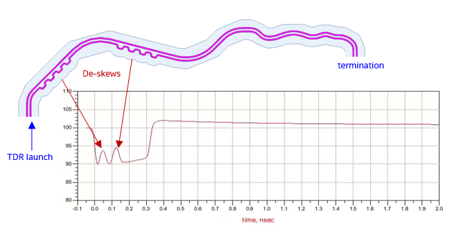
The figure below shows an impedance discontinuity example due to trace de-skew. The most common way to de-skew P/N lanes in a differential pair is to use the trace trombone configuration. As you can see in the TDR performance of the trace in the figure, the impedance of the differential pair fluctuates due to the discontinuity in that trombone region. In this example, the differential pair is routed on the top layer and has tight coupling between the P/N legs , i.e. Zodd << Zeven. It appears there are 4-ohm Zdiff bumps in the TDR performance curve that eventually cause a return loss penalty.
Figure 18. Impedance Discontinuity Example Due to Trace De-skew
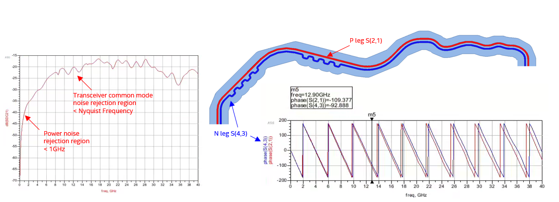
The following figure also shows a mode conversion example due to trace de-skew. In this example, the delay difference between the P and N legs as well as the measured trace lengths end-to-end are the same in the layout tool. However, through simulation, the P leg delay is about 17 degrees or 3.5 ps longer than the N leg delay at the Nyquist frequency (12.9 GHz). The delay difference between the P and N legs increases at higher frequencies. The common mode to differential mode conversion is about -20 dB.
Figure 19. Mode Conversion Example Due to Trace De-skew
The figure below illustrates some routing recommendations for trace de-skew to avoid both an impedance mismatch and mode conversion.
Trace De-Skew Trombone Consideration for Tightly Coupled Differential Pairs
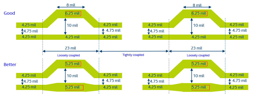
Widening the trace segments with loosely coupled P/N legs will help with impedance compensation and reduce the impedance in that region. The figure below illustrates good and better implementations of the trace de-skew trombone configuration.
Figure 20. Improving Impedance Matching in Trace De-skew Trombone Configuration
Trace De-Skew Length Matching Consideration for Differential Pair
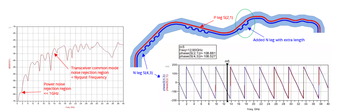
Adding extra length on the leg with more de-skew trombone will help compensate for the trace delay for better de-skewing. However, simulations or lab measurements are required to determine the extra lengths needed in layout. The following figure shows the N leg with added length. The common mode to differential mode conversion improves by an extra 19 dB at 12.9 Ghz and by 25 dB at 1 GHz compared to the example shown in the figure Mode Conversion Example Due to Trace De-skew above.
Figure 21. Improving Mode Conversion in Trace De-skew Trombone Configuration