Intel® Quartus® Prime Pro Edition User Guide: Power Analysis and Optimization
ID
683174
Date
6/22/2022
Public
A newer version of this document is available. Customers should click here to go to the newest version.
1.3.2.1. Using Simulation Signal Activity Data in Power Analysis
1.3.2.2. Signal Activities from RTL (Functional) Simulation, Supplemented by Vectorless Estimation
1.3.2.3. Signal Activities from Vectorless Estimation and User-Supplied Input Pin Activities
1.3.2.4. Signal Activities from User Defaults Only
1.5.1. Complete Design Simulation Power Analysis Flow
1.5.2. Modular Design Simulation Power Analysis Flow
1.5.3. Multiple Simulation Power Analysis Flow
1.5.4. Overlapping Simulation Power Analysis Flow
1.5.5. Partial Design Simulation Power Analysis Flow
1.5.6. Vectorless Estimation Power Analysis Flow
2.4.1. Clock Power Management
2.4.2. Pipelining and Retiming
2.4.3. Architectural Optimization
2.4.4. I/O Power Guidelines
2.4.5. Dynamically Controlled On-Chip Terminations (OCT)
2.4.6. Memory Optimization (M20K/MLAB)
2.4.7. DDR Memory Controller Settings
2.4.8. DSP Implementation
2.4.9. Reducing High-Speed Tile (HST) Usage
2.4.10. Unused Transceiver Channels
2.4.11. Periphery Power reduction XCVR Settings
1.3.2.1.1. Generating Signal Activity Data for Power Analysis
Follow these steps to generate and use simulation signal activity data for power analysis:
- To run full compilation on your design, click Processing > Start Compilation.
- To specify settings for output of simulation files, click Assignments > Settings > EDA Tool Settings > Simulation. Select your simulator in Tool name and the Format for output netlist and Output directory.
- Turn on Map illegal HDL characters. This setting directs the EDA Netlist Writer to map illegal characters for VHDL or Verilog HDL, and results in more accurate data for power analysis.
Figure 7. EDA Tool Settings for Simulation
- For Intel® Stratix® 10 designs, to generate a Standard Delay Output (.sdo) file that includes back-annotation of delays for power analysis, refer to Generating Standard Delay Output for Power Analysis.
- In the Intel® Quartus® Prime software, click Assignments > Settings > Power Analyzer Settings.
- Under Input file, turn on Use input files to initialize toggle rates and static probabilities during power analysis.
Figure 8. Specifying Power Analysis Input Files
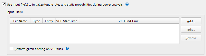
- To specify a .vcd for power analysis, click Add and specify the File name, Entity, and Simulation period for the .vcd, and click OK.
- To enable glitch filtering during power analysis with the .vcd you generate, turn on Perform glitch filtering on VCD files.
- To run the power analysis, click Start on the Power Analysis step in the Compilation Dashboard. View the toggle rates in the power analysis results.