Developer Guide
Intel oneAPI DPC++/C++ Compiler Handbook for Intel FPGAs
A newer version of this document is available. Customers should click here to go to the newest version.
I/O Pipes
An I/O pipe is a unidirectional (source or sink) connection to the hardware that may be connected to input or output features of an FPGA board. These features might include network interfaces, PCIe®, cameras, or other data capture or processing devices or protocols.
A source I/O device provides data that a SYCL kernel can read whereas a sink I/O device accepts data written by a SYCL kernel and sends it to the hardware device. A common use of I/O pipes is to interface to ethernet connections that interface directly with the FPGA. The source reads from the network and the sink writes to the network. This allows a SYCL kernel to process data from the network and resend it back to the network.
For testing purposes, you can use files on the disk as input or output devices, allowing you to debug using emulation or simulation for faster compilation.
I/O Pipes Implementation
To implement I/O pipes, follow these steps:
- Consult your board vendor documentation before you implement I/O pipes in your kernel program.
- Use a struct with a numeric id to define a kernel_readable_io_pipe or kernel_writable_io_pipe type to declare an I/O pipe to interface with hardware peripherals. These definitions are typically provided by a board vendor.
- The numeric id value is the 0-origin index into the interfaces in the channels section of the board_spec.xml for the device.
- The chan_id argument is necessary for simulation and it is the name of the I/O interface listed in the board_spec.xml file as shown in the following:
 <channels>
   <interface name="board" port="c1"  type="streamsource" width="32" chan_id="c1"/>
   <interface name="board" port="c2"  type="streamsink" width="32" chan_id="c2"/>
 </channels>
NOTE:Only channels marked type streamsource or streamsink are used for indexing.
- Implement the interface to hardware I/O pipes or files (emulator or simulator) by mapping the id variable, as shown in the following:
// Specialize a pipe type
struct read_io_pipe {
  static constexpr unsigned id = 0;
};

struct write_io_pipe {
  static constexpr unsigned id = 1;
};

// id 0 -> file name or channel name: "c1" for hardware, "0" for emulator, "c1" for simulation.
using read_iopipe = ext::intel::kernel_readable_io_pipe<read_io_pipe, unsigned, 4>;

// id 1 -> file name or channel name: "c2" for hardware, "1" for emulator, "c2" for simulation.
using write_iopipe = ext::intel::kernel_writeable_io_pipe<write_io_pipe, unsigned, 3>;
where:
Interface Description For Hardware id N is mapped to the channel (not file) in the associated hardware. For example: - id 0 is mapped to the chan_id in the first interface defined.
- id 1 is mapped to the chan_id in the second interface defined, and so on.
If there is no matching channel, an error is generated.
For Emulator id N is mapped to a file named N, which means id 0 is file "0". This file is read or written by reading or writing to the associated I/O pipe. For Simulator id N is mapped to chan_id names in the board_spec.xml file supplied with the BSP (See channels). For example: - id 0 is mapped to the chan_id in the first interface defined.
- id 1 is mapped to the chan_id in the second interface defined, and so on.
If there is no matching channel, an error is generated.
The I/O Pipe Classes and Their Use
The I/O pipe APIs exposed by the FPGA implementations is equivalent to the following class declarations:
template <class name,
          class dataT,
          size_t min_capacity = 0>
class kernel_readable_io_pipe {
  public:
    static dataT read();  // Blocking
    static dataT read(bool &success_code);  // Non-blocking
};

template <class name,
          class dataT,
          size_t min_capacity = 0>
class kernel_writeable_io_pipe {
  public:
    static void write(dataT data);  // Blocking
    static void write(dataT data, bool &success_code);  // Non-blocking
}
The following table describes the template parameters:
Parameter |
Description |
|---|---|
| name | The type that is the basis of an I/O pipe identification. It may be provided by the device vendor or user defined. The type must contain a static constexpr unsigned expression with name id, which is used to determine the hardware device referenced by the I/O pipe. |
| dataT | The type of data packet contained within an I/O pipe. This is the data type that is read during a successful pipe read() operation, or written during a successful pipe write() operation. The type must have a standard layout and be trivially copyable. |
| min_capacity | User-defined minimum number of words (in units of dataT) that an I/O pipe must be able to store without any being read out. The compiler may create an I/O pipe with a larger capacity due to performance considerations. |
A data word in this context is the data type that the pipe contains (dataT pipe template argument).
Example Code for I/O Pipes
Here is an example that includes the definitions above:
// "Built-in pipes" provide interfaces with hardware peripherals
// These definitions are typically provided by a device vendor and
// made available to developers for use.
namespace example_platform {
  template <unsigned ID>
  struct ethernet_pipe_id {
    static constexpr unsigned id = ID;
  };

  using ethernet_read_pipe = kernel_readable_io_pipe<ethernet_pipe_id<0>, int, 0>;
  using ethernet_write_pipe = kernel_writeable_io_pipe<ethernet_pipe_id<1>, int, 0>;
}Using I/O Pipes to Stream Data
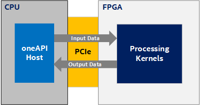
In many of the design examples, an FPGA device is treated as an accelerator, as illustrated in the following diagram, where the main computation (and therefore the data to be computed) resides on the host (CPU) and you accelerate some compute-intensive task using kernels on the device. The host moves the data to the device, performs the calculation, and moves the data back:
However, a key feature of FPGAs is their rich input-output (I/O) capabilities (for example, Ethernet). Taking advantage of these capabilities within the oneAPI programming environment requires a different programming model than the accelerator model as described above. In the model illustrated in the following figure, consider a kernel (or kernels) where some of the kernels are connected to the FPGA's I/O via I/O pipes and the main data flow is through the FPGA device rather than from CPU to FPGA and back:
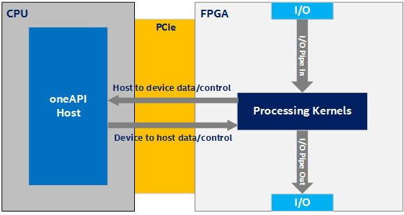
In the Figure 2, there are four possible directions of data flow:
- I/O to device
- Device to I/O
- Device to host
- Host to device
The direction and amount of data flowing in the system is application dependent. The main source of data is I/O. Data streams into the device from I/O (I/O to device) and out of the device to I/O (device to I/O). However, the host and device exchange low-bandwidth control signals using a host-to-device and device-to-host connection (or side channel).
I/O pipes have the same interface API as inter-kernel pipes. This abstraction is implemented in the Board Support Package (BSP) and provides a much simpler programming model for accessing the FPGA I/O. See The I/O Pipe Classes and Their Use.
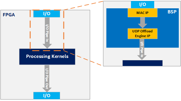
Consider an example scenario where you want the kernel to be able to receive UDP packets through the FPGA's Ethernet interface. Implementing the necessary hardware to process the data coming from the Ethernet pins in oneAPI would be both extremely difficult and inefficient. Moreover, there are already many RTL solutions for doing this. So, instead, you can implement this low-level logic with RTL in the BSP. This example is illustrated in the following figure, where the BSP connects the Ethernet I/O pins to a MAC IP, the MAC IP to a UDP offload engine IP, and finally the UDP offload engine IP to an I/O pipe. This I/O pipe can then be simply connected to the processing kernels. The details of these connections are abstracted from the oneAPI kernel developer. The following figure shows only an input I/O pipe. The process is similar for an output I/O pipe, but the data flows in the opposite direction.
Faking I/O Pipes
Unfortunately, designs that use these I/O pipes are confined to BSPs that support that specific I/O pipe, which makes prototyping and testing the processing kernels difficult. To address these concerns, a fake I/O pipes library is available. With this library, you can create kernels that behave like I/O pipes without having a BSP that actually supports them. This allows you to start prototyping and testing your processing kernels without a BSP that supports I/O pipes.
There are currently two options for faking IO pipes:
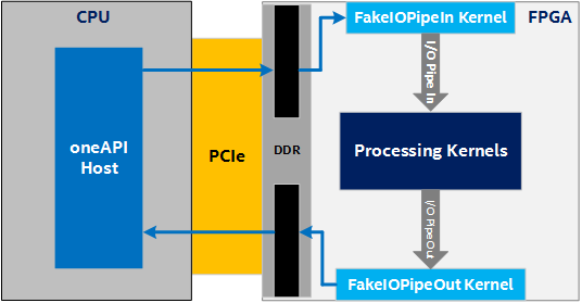
- Device memory allocations: This option requires no special BSP support, as shown in the following figure:
Device Memory Allocations
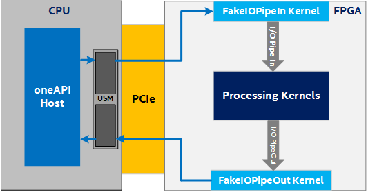
- Unified Shared Memory (USM) host allocations: This option requires USM support in the BSP as shown in the following figure. See also Unified Shared Memory topic in the open-access book Data Parallel C++: Programming Accelerated Systems Using C++ and SYCL*.
Unified Shared Memory (USM) Host Allocations