Developer Guide
Intel oneAPI DPC++/C++ Compiler Handbook for Intel FPGAs
A newer version of this document is available. Customers should click here to go to the newest version.
Concepts of FPGA Hardware Design
FPGA designs are subject to constraints and tradeoffs in the following areas:
Maximum Frequency (fMAX)
The maximum clock frequency at which a digital circuit can operate is called its fMAX. This is the maximum rate at which the outputs of registers are updated.
The physical propagation delay of the signal across combinational logic between two consecutive register stages limits the clock speed. This propagation delay is a function of the complexity of the combinational logic in the path. The path with the most combinational logic elements (and the highest delay) limits the speed of the entire circuit. This speed-limiting path is often referred to as the critical path (see Figure 1).
The fMAX is calculated as the inverse of the critical path delay. You may want to have high fMAX since it results in high performance in the absence of other bottlenecks.
Latency
Latency is the measure of how long it takes to complete one or more operations in a digital circuit. You can measure latency at different granularities. For example, you can measure the latency of a single operation or the latency of the entire circuit.
You can measure latency in time (for example, microseconds) or clock cycles. Typically, clock cycles are the preferred way to express latency because measuring latency in clock cycles disconnects latency from your circuit clock frequency. By expressing latency independent of circuit clock frequency, it is easier to discern the true impact of circuit changes to the circuit's performance.
For more information and an example, refer to Pipelining.
Pipelining
Pipelining is a design technique used in synchronous digital circuits to increase fMAX. Pipelining involves adding registers to the critical path, which decreases the amount of logic between each register. Less logic takes less time to execute, which enables an increase in fMAX.
The critical path in a circuit is the path between any two consecutive registers with the highest latency. That is, the path between two consecutive registers where the operations take the longest to complete.
Pipelining is especially useful when processing a stream of data. A pipelined circuit can have different stages of the pipeline operating on different input stream data in the same clock cycle, which leads to better data processing throughput.
Pipelining Example
Consider a simple circuit with operations A and B on the critical path. If operation A takes 5 ns to complete and operation B takes 15ns to complete, then the time delay on the critical path is 20 ns. This results in an fMAX of 50 MHz (1/max_delay).

If a pipeline register is added between A and B, the critical path changes. The delay on the critical path is now 15ns. Pipelining this block results in an fMAX of 66.67 MHz, and the maximum delay between two consecutive registers is 15 ns.
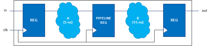
While pipelining generally results in a higher fMAX, it increases latency. In the previous example, the latency of the block containing A and B increases from two to three clock cycles after pipelining.
Throughput
Throughput of a digital circuit is the rate at which data is processed. In the absence of other bottlenecks, higher fMAX results in higher throughput (for example, samples/second).
Throughput is a good measure of the performance of a circuit, and throughput and performance are often used interchangeably when discussing a circuit.
Datapath
A datapath is a chain of registers and combinational logic in a digital circuit that performs computations.
For example, the datapath in Figure 2 consists of all elements shown, from the input register to the last output register.
In contrast, memory blocks are outside the datapath and reads and writes to memory are also considered to be outside of the datapath.
Control Path
While the datapath is the path on which computations occur, the control path is the path of signals that control the datapath circuitry.
The control path is the logic added by the compiler to manage the flow of data through your design. Control paths include controls such as the following:
| Control | Description |
|---|---|
| Handshaking flow control | Handshaking ensures that one part of your design is ready and able to accept data from another part of your design. |
| Loop control | Loop controls control the data flow through the hardware generated for loops in your code, including any loop carried dependencies. |
| Branch control | Branch controls implement conditional statements in your code. Branch control can include parallelizing parts of conditional statements to improve performance. |
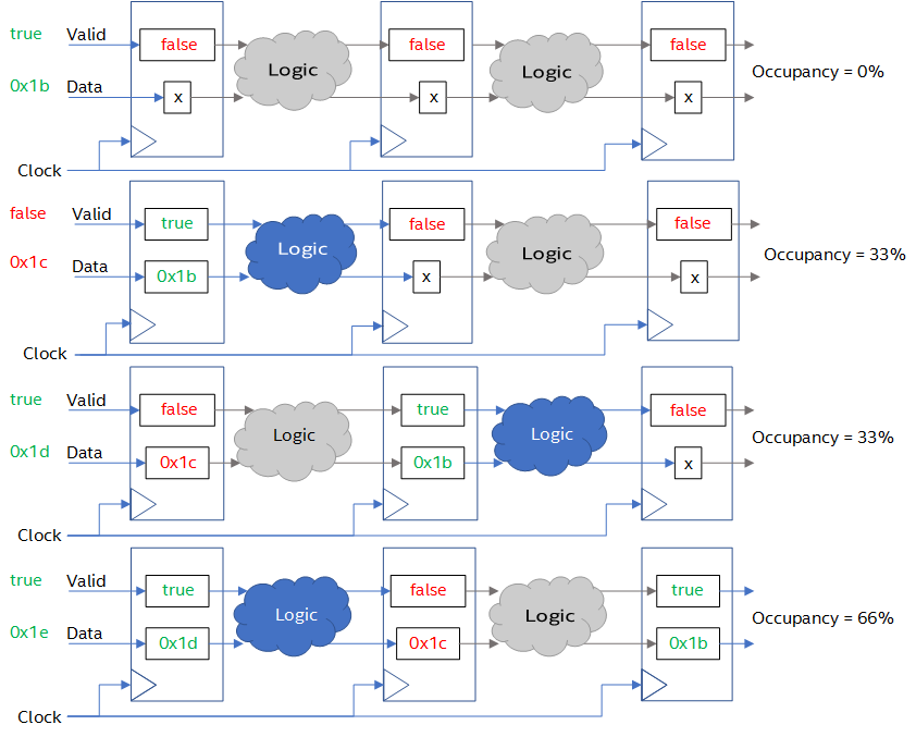
Occupancy
The occupancy of a datapath at a point in time refers to the proportion of the datapath that contains valid data. The occupancy of a circuit over the execution of a program is the average occupancy over time from the moment the program starts to run until it has been completed.
Unoccupied portions of the datapath are often referred to as bubbles. Bubbles are analogous to no-operation (no-ops) instructions for a CPU that have no effect on the final output.
Decreasing bubbles increase occupancy. In the absence of other bottlenecks, maximizing occupancy of the datapath results in higher throughput.