1G/2.5G/5G/10G Multirate Ethernet PHY Intel® FPGA IP User Guide: Agilex™ 3 and Agilex™ 5 FPGAs and SoCs
ID
813667
Date
4/07/2025
Public
A newer version of this document is available. Customers should click here to go to the newest version.
1. About the 1G/2.5G/5G/10G Multirate Ethernet PHY Intel® FPGA IP for Agilex™ 3 and Agilex™ 5 Devices
2. Getting Started
3. Functional Description
4. Parameter Settings for 1G/2.5G/5G/10G Multirate Ethernet PHY Intel® FPGA IP
5. Interface Signals
6. Configuration Registers
7. Debug Checklist
8. 1G/2.5G/5G/10G Multirate Ethernet PHY Intel® FPGA IP User Guide: Agilex™ 3 and Agilex™ 5 FPGAs and SoCs Archives
9. Document Revision History for the 1G/2.5G/5G/10G Multirate Ethernet PHY Intel® FPGA IP User Guide: Agilex™ 3 and Agilex™ 5 FPGAs and SoCs
3.2.1.1. Step 1: Generating the 1G/2.5G/5G/10G Multirate Ethernet PHY IP
3.2.1.2. Step 2: QSF settings and Dynamic Reconfiguration (DR) profile assignments
3.2.1.3. Step 3: RTL Generation using Quartus® Prime Pro Edition Tool
3.2.1.4. Step 4: Instantiate the IP top file with the GTS Dynamic Reconfiguration Controller IP
5.1. Clock Signals
5.2. Reset Signals
5.3. Serial Interface Signals
5.4. Avalon Memory-Mapped Interface Signals
5.5. XGMII Signals
5.6. GMII Signals
5.7. PHY Status Signals
5.8. Transceiver Mode and Operating Speed Signals
5.9. Transceiver Status and Reconfiguration Signals
5.10. GTS Reset Sequencer Signals
5.11. Dynamic Reconfiguration Controller Interface Signals
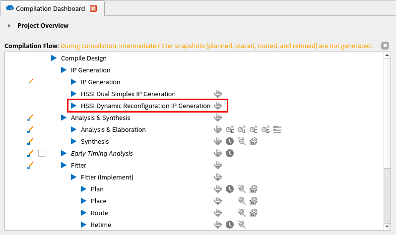
3.2.1.3. Step 3: RTL Generation using Quartus® Prime Pro Edition Tool
- Execute the HSSI Dynamic Reconfiguration IP Generation through the Quartus® Prime Pro Edition compilation dashboard as shown in figure below to generate the RTL for the DR group. This process utilizes the .ip file of the 1G/2.5G/5G/10G Multirate Ethernet PHY IP (mrphy_1g_2p5g.ip) along with the project settings .qsf file to create the new top-level RTL file for DR group (mr_top.sv).
- The new IP top-level RTL file (mr_top.sv) includes all IP components required to interface with the GTS Dynamic Controller IP.
- As shown in the below figure, the new IP top-level RTL file contains the changes to interface signal names:
- The clock signals, reset signals, and other interface signals for the 1G/2.5G/5G/10G Multirate Ethernet PHY IP are appended with the <instance name> as defined in the .qsf file (_inst_mrphy_1g_2p5g_).
- The TX/RX serial interface signals and the request and grant signals from GTS reset sequencer (o_src_rs_req and i_src_rs_grant) are appended with the channel number (_ch0_). The clock signal name, pma_cu_clk is appended with “bank0”.
- The new DR controller Avalon® memory-mapped interface signals (<i/o>_dr_lavmm_<signal_name>_ch<n>) is added to the top-level RTL file for configuring the GTS PMA Direct PHY IP. This should be connected to the GTS Dynamic Reconfiguration Controller IP. The interface signal names are appended with the channel number.
- The new interface signal one_hot_sel[profiles-1:0] is added to the top-level RTL file for the profile selection and this must be connected to the GTS Dynamic Reconfiguration Controller IP.
- The IP generates single .mif file (mr_top.mif) for all the profiles of the 1G/2.5G/5G/10G Multirate Ethernet PHY and the RTL generated is both simulatable and compilable.
Figure 9. Module Hierarchy and Interface Naming Changes Post-Dynamic Reconfiguration Flow